Article by: Johan
Applies to: all e32 and e34 models.
Introduction: The IHKA system (Intergriertes Heizung und Klima Automatic) is probably one of the systems that will cause you some major headaches over the course of your E32 ownership. The system seems really complex, but once you get a better understanding of it the system isn’t that scary anymore.
I hope after reading this you have a better idea of all the parts in the system. I will not at this time discuss the working of the system or the component removal as you probably all have a Bentley manual (unlike me). As for the interior removal you can see how to get to most of the parts by looking at the “dashboard removal” and “center vents” sections of this webpage.
The climate control system of the E32 is not a completely automatic control system as it doesn’t vary the fan speed on it’s own. It does regulate the temperature on it’s own. The system consists of a number of parts which will all be handled in the following paragraphs. The parts are:
Part list:
- stepper motors
- temperature sensors
- air flaps
- the control panel
- the control unit
- the fan
- the fan speed controller
- the heater parts (heater core, water valves and aux water pump)
- Air conditioner specific parts (evaporator, expansion valve, compressor, condenser, aux. fan, pressure switches and the dryer)
Parts and Locations:
Stepper motors:
There are ten stepper motors in the system. These are all the same motors, but two have a different connection part (mixing flaps). The motors control the flaps for:
- 1. Passenger side foot well flap
- 2. Passenger side dash vent flap
- 3. Passenger side temperature mixing flap
- 4. Driver side foot well flap
- 5. Driver side dash vent
- 6. Driver side temperature mixing flap
- 7. Outside air flaps
- 8. Recirculation mode flap
- 9. Demister vents flap
- 10. Rear passengers fresh air flap
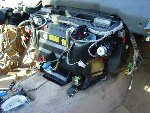
fig 1.1 stepper motors on IHKA housing
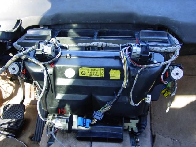
fig 1.2 stepper motors on IHKA housing
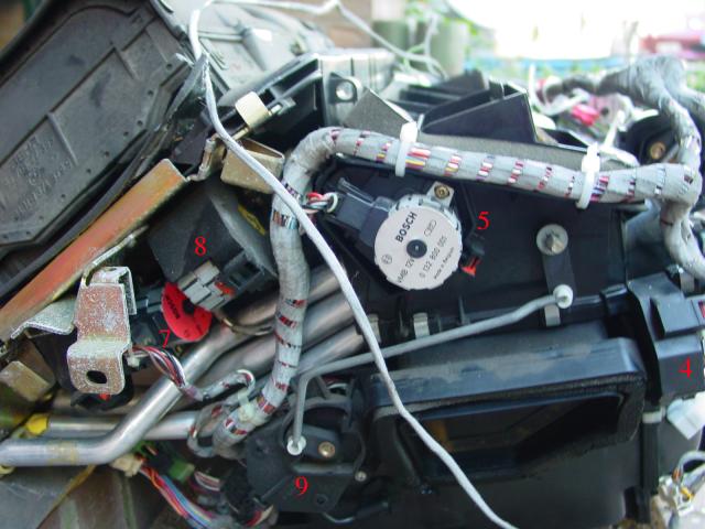
fig 1.3 stepper motors on IHKA housing
Temperature sensors:
There are five temperature sensors in the system:
- 1. Passenger side heater core temperature sensor
- 2. Driver side heater core temperature sensor
- 3. Control panel temperature sensor
- 4. Evaporator temperature sensor
- 5. Outside temperature sensor
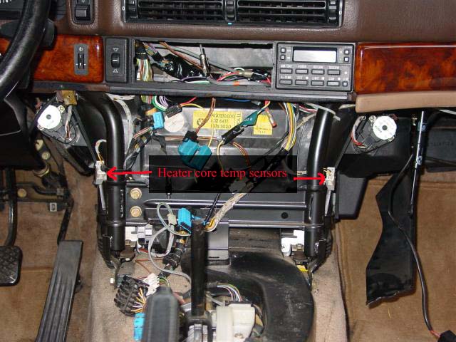
fig 2.1 Driver/passenger temp sensor on the housing.
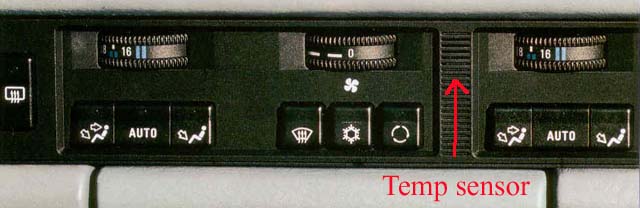
fig 2.2 Control panel temp sensor
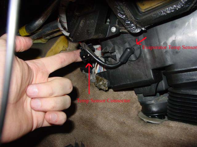
fig 2.3 Evaporator temp sensor on the left side of the housing
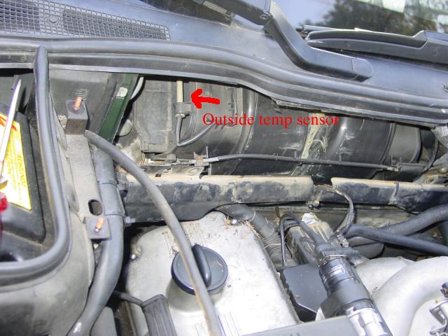
fig 2.4 Outside temperature sensor behind bulkhead panel.
| Temperature | Resistance |
| 0 C / 32 F | 2.69 - 3.46 kOhm |
| 10 C / 50 F | 1.74 - 2.11 kOhm |
| 20 C / 68 F | 1.15 - 1.32 kOhm |
| 25 C / 77 F | 0.95 - 1.05 kOhm |
| 30 C / 86 F | 0.76 - 0.87 kOhm |
| 40 C / 104 F | 0.49 - 0.60 kOhm |
| Temperature | Resistance |
| -20 C / -4 F | 84.39 - 109.61 kOhm |
| -10 C / 14 F | 48.58 - 62.09 kOhm |
| 0 C / 32 F | 28.89 - 36.40 kOhm |
| 20 C / 68 F | 11.13 - 13.83 kOhm |
| 60 C / 140 F | 2.19 - 2.78 kOhm |
| 100 C / 212 F | 0.58 - 0.77 kOhm |
| Temperature | Resistance |
| -5 C / F | 11.4 - 11.9 kOhm |
| 0 C / F | 8.8 - 9.2 kOhm |
| 5 C / F | 6.8 - 7.2 kOhm |
| 10 C / F | 5.3 - 5.6 kOhm |
| 15 C / | 4.2 - 4.5 kOhm |
| 20 C / F | 3.3 - 3.6 kOhm |
| 25 C / F | 2.6 - 2.9 kOhm |
| 30 C / F | 2.1 - 2.3 kOhm |
| 35 C / F | 1.7 - 1.9 kOhm |
You can check the temperature sensors for proper operation by measuring their resistance. The fridge comes in handy here . . . and while you are near the fridge . . . might as well grab a beer ; )
Air flaps / air ducts: There are 10 air flaps in the system. Makes sense as there are also 10 stepper motors.
- Defroster air flaps
- Passenger side center vents flap
- Driver side center vents flap
- Passenger side mixing flaps
- Driver side mixing flaps
- Passenger side foot well air flap
- Driver side foot well air flap
- Rear passenger fresh air flap
- Outside air flaps
- Recirculation air flap
The system also has eight air ducts:
- left side defroster duct
- right side defroster duct
- left side in-dash vents ducts
- right side in dash vent duct
- center vents ducts
- rear passenger air ducts
- left side rear passenger air duct
- right side rear passenger air ducts
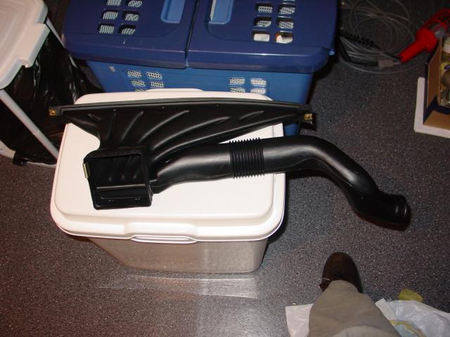
fig 3.1 Left side defroster air duct
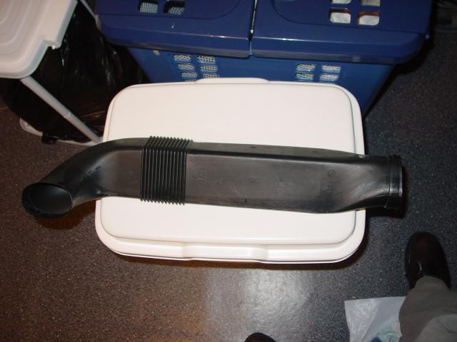
fig 3.2 Left side in-dash duct
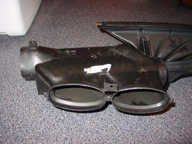
fig 3.3 Old style center vents ducts (pre 06/88)
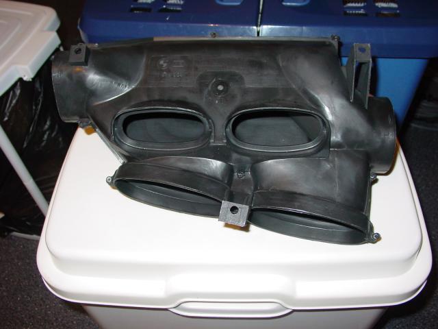
fig 3.4 New style center vents ducts (post 06/88)
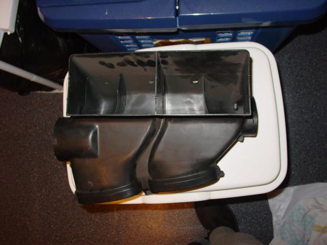
fig 3.5 New style center vents ducts from the underside.
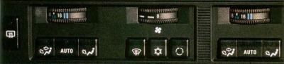
fig 4.1 Control panel without AUC
This is one of the few parts you all have seen 🙂
Control unit: The control is mounted behind the heater core.
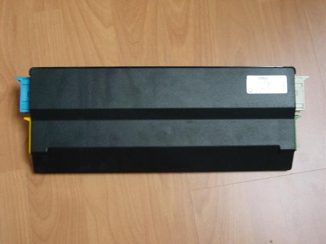
fig 5.1 IHKA Control unit.
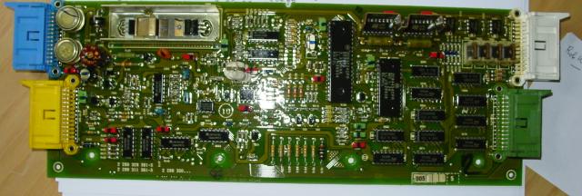
fig 5.2 IHKA Control unit PCB
Blower: The fan blower is located in front of the heater core. It’s speed is controlled by the so called sword.
The sword is located in between the evaporator and the control unit. Erratic fan behavior is often caused by the sword.
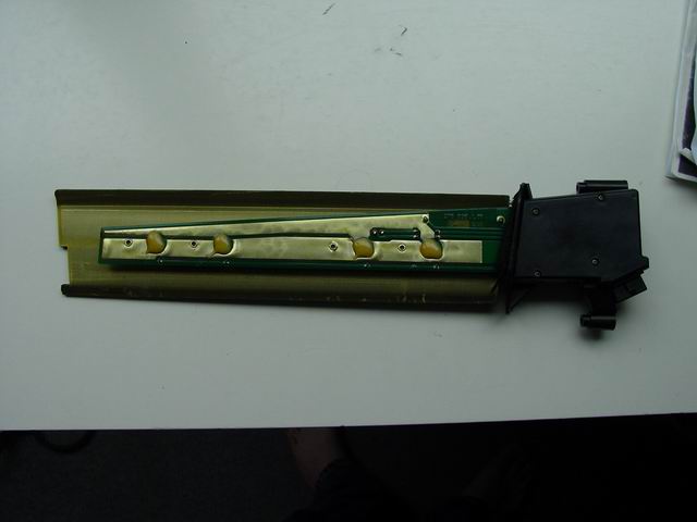
fig. 6.1 “the sword”.
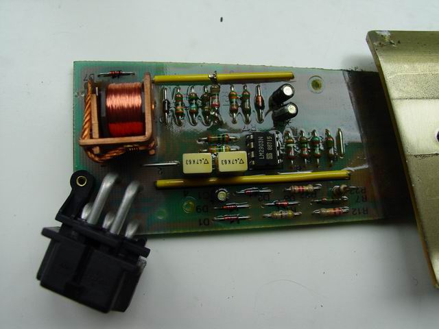
fig 6.2 sword PCB
Heater specific parts:
- Heater core
- Heater valves
- Aux water pump
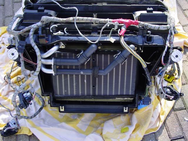
fig 7.1 Heater core.
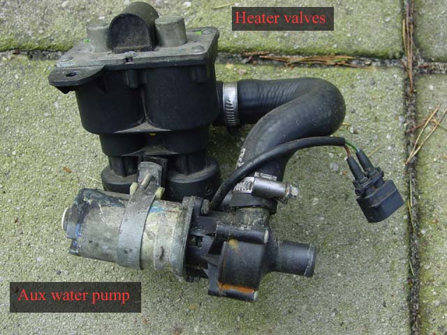
fig 7.2 Water valves and aux water pump.
Air conditioner specific parts:
- Evaporator
- Expansion valve
- Compressor
- Compressor relays
- Condenser
- Aux fan
- Aux fan ballast resistor
- Pressure switch
- Dryer
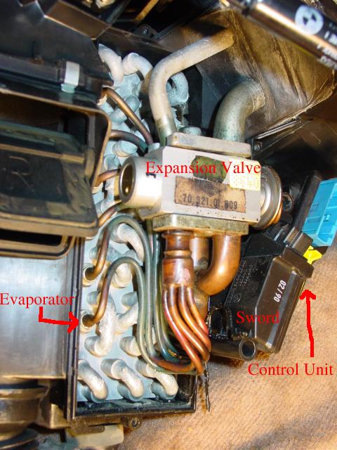
fig 8.1 Evaporator, Expansion valve, Sword and Control unit
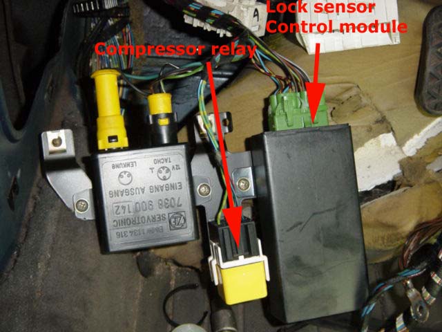
fig 8.2 Compressor relays located behind the driver side speaker kick panel. Picture by Cor.
As the 750i has two motronic systems the “compressor on” signal is send via the lock sensor control module.
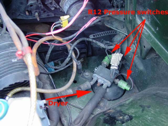
fig 8.3 Dryer with pressure switches (R12 uses 3 switches, R134a uses 1)
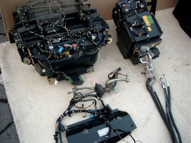
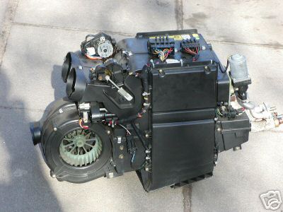
Highline:
If your 750iL came with a ‘Highline’ package you will have a second IHKA setup under the rear part of the center console.
Just to make things more complicated this box came with it’s own heater core, evaporator, water valve, control unit,…etc.
Some pictures of the extra heater box: