Article by: Max F
Applies to: early E24, E31 (850), and early E32 (735 and 750) models.
The ATE brand hydraulic brake booster on the older E32 vehicles is one of the oddities of the model. The system, known to BMW as the ‘H31’ system, runs the brake boost with high pressure hydraulic fluid from the power steering system – not with intake manifold vacuum as is usual on most cars.
The overall system looks like this:
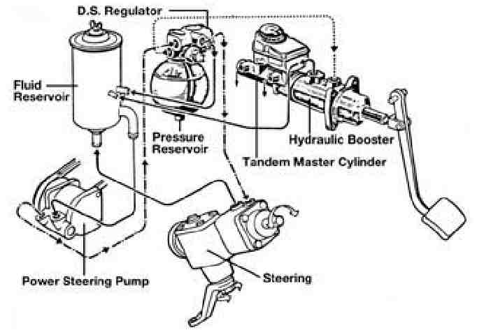
The brake master cylinder itself is a standard tandem dual-circuit system, feeding the normal ABS modulator unit with normal brake fluid. The booster runs ATF or special “Pentosin” fluid if the car has LAD (load adjusting) rear suspension. Pump pressure is max 130 bar (read ~2000psi) so the system includes the extra refinement of the regulator and pressure reservoir to allow for use with braking… the regulator holds the boost pressure at a constant 52-57 bar, includes switches to warn of loss of pressure, and allows for pressurizing the nitrogen-charged “brake bomb”. The “bomb” allows for about 10 boost-assisted braking even with the engine stopped – required for brakes. Under normal use, only about 10% maximum of the pump flow ever goes to the brakes, the rest is used by the steering (and if that’s not requiring boost, the continual flow gets bypassed and circulates around, including going back to the reservoir via the cooling loop in front of the radiator, and through the filter present in some of the reservoirs).
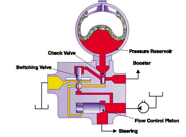
The internals of the regulator look like this: the main thing to note is that the majority of the fluid goes straight through to the steering box under most circumstances – if we remove the booster, we can still have the system function . . .
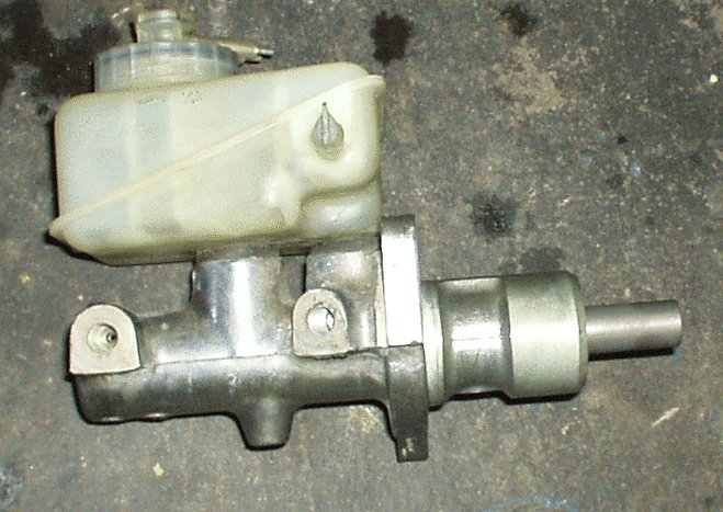
The booster itself looks like this:
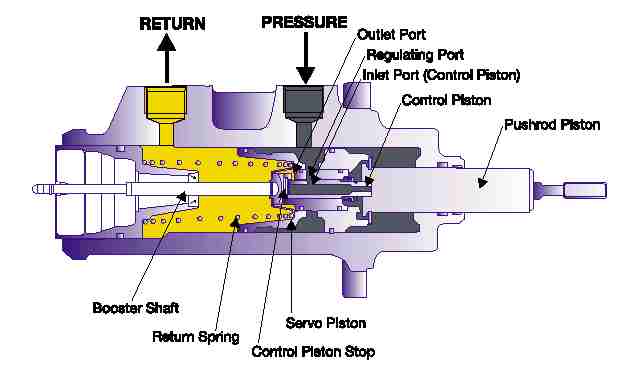
The push rod goes to the pedal; the booster shaft into the brake master cylinder.
The main principle here is the small amount of normal force on the brake pedal controls the “control piston”, which pressurizes behind the larger “servo piston” and gets that 800 or so PSI of pressure to do most of the work.
The yellow area is at zero/return rate pressure only.
SO – what’s my problem?
The booster system is complex.
My booster was leaking from the low-pressure end – A new booster costs $1300NZ from the dealer.
My problems were probably only half-way through. (Explanation: I’d used new ATF recently, and since that change the car had blown the seals on the pump AND now the booster had started leaking.
ATF is highly detergent, and I think the new stuff was uncovering lots more holes.
If I assumed the brake bomb was due soon too, I’d have to add another ~$500NZ to by repairs . . . Then what else??!)
In finding the leaking booster, my dealer had also condemned the old master cylinder as leaking too – add another $1000NZ.
I was up for at least $2300 on parts alone (possibly $2800) on a car worth about $7000 . . .
I decided to not play that game. The later E32s, where space permitted, used the vacuum booster system the E34 (5 series) used all the time.
Checking the ETK, they were the same part; more importantly for my retrofit, the ABS pump and bodies from my early (1988) E32 were the same as those used for these later (1992+) E32s with this vacuum system.
I could probably retrofit an E34 vacuum system to my early E32, and just not play the “fix the H31” game.
Wrecker cost for an E34 booster, master cylinder & lines to the ABS unit – $200NZ.
What about me?! I can’t replace the H31 booster, my model can’t take it etc etc – For more information about the H31 system: SEE HERE.
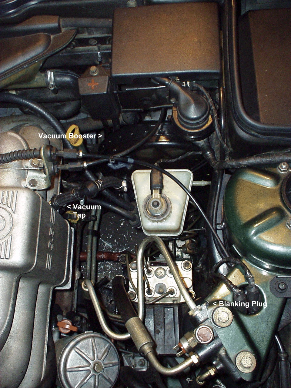
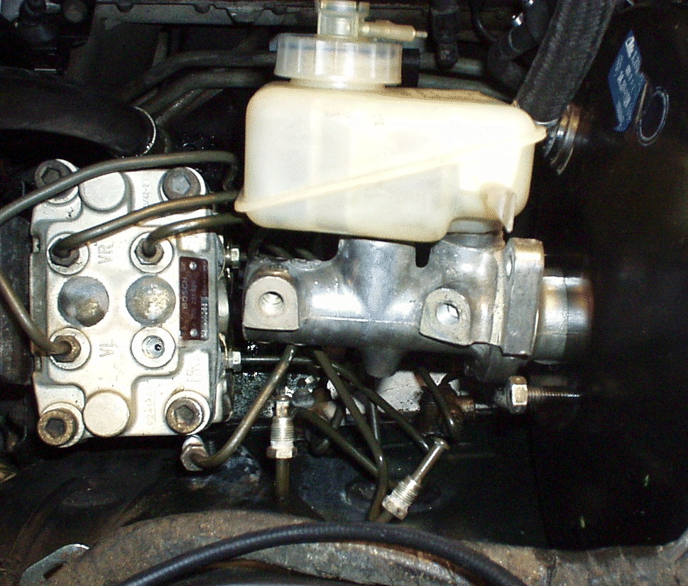
How do you do it? Have a good look at your car as it is now.
Here’s roughly how mine looked (remember, they look the same, RHD or LHD):
You are going to be:
- Removing the old brake master cylinder and the H31 booster
- Blanking off the H31 pressure feed at the regulator
- Blocking off the low-pressure return line
- Fitting a vacuum booster
- Fitting a new master cylinder
- Tapping a hole into your intake manifold for vacuum take-off.
It will end up looking like this:
So . . . can you do this?
I think can you do this – it’s your skills.
Think about legal implications: under law here in NZ, I could get away with this as I was using drop-in parts with a design approved for my model by the manufacturer (the 1992-onwards E32s with the vacuum system standard) – but I did have to go through the process of discussing this with the road-worthiness certificate issuer (at the local dealer) to stay legal & insured.
You need to think this through for your local laws.
Think do you want to customize the intake manifold – this is the one major corner I’ve cut, aesthetically.
I’ve not bothered taking a whole vacuum-tapped manifold from a donor engine: I’ve irrevocably modified mine (in a professional manner, I’d like to think). Your call. Still interested? If so, read on.
1) Talk nicely to the wrecker. Get an 535 E34, measure from firewall to rearmost “face” of the ABS controller.
Measure on your car… check that they match. Make sure it’s a 535, you want a booster “rated” for the vacuum off the M30 3.5l big six, not something unknown.
2) Get E34 unit out and remove:
a) The pin from the pedal (once clip freed)
b) Four 13mm bolts around pedal push rod (holds booster to firewall)
c) Vacuum hose to intake manifold (careful, woven outer included 3 spirals of sharp springy wire).
d) Two steel brake lines going from master cylinder to the ABS controller. Can be very stubborn; “crack” their lock with vice-grips then undo. DO NOT mangle the nuts…! In my case the E34 ‘donor’ had an empty engine bay, so I could just lift the unit out, but if you don’t have lots of space, jump ahead a bit and see how I separated the MC from the booster to get them in.
OK – you should be OK to use this to get them out as well. (NB steel brake lines can be GENTLY bent without damage – just don’t bend to too tight a curve.)
3) Consider the vacuum non-return valve. E34s have a tapping cast into the manifold; your car won’t have one. In my case I tapped my own take-off hole in my existing manifold and used a valve from an E36 325, rather than try to contemplate a complete manifold swap. If you’re swapping the manifold, then take care with the valve. If you are not, get a valve somewhere else and some hose too.
Word to the wise: The vacuum must be tapped AFTER the throttle butterfly; I did try a tap from the rubber AFM-throttle duct, with abysmal results – no vacuum at all, really. You do have to get it from the manifold.
4) Take your prizes home.
5) Get the following supplies:
- Plenty of brake cleaner (need VERY clean unions for the MC brake lines – I use the “no residue”, “safe for inside & outside” stuff in an aerosol can with the little spray “straw” thing).
- Rags (to collect the pint or so of ATF in the booster)
- Teflon thread-sealer tape
- Brake fluid (for the bleed on reassembly – I found a liter was enough, but YMMV)
- Brake bleeding tools
- Normal metric socket set
- A good torque wrench (vacuum boosters can be ruined if you over tighten the master cylinder onto them)
- Brake-seal safe grease
- Wire cutters
- Lino (“Stanley”) knife
- Tap & die set
- Brass threaded hose take-off ** (depends on your hose used/salvaged & your Tap/die set)
- Drill for tapping process (pref. speed controlled, so you can keep as much crap out as possible)
- Small STRONG adjustable wrench (brake lines are not metric, nor imperial – I think they’re either SAE or AF. You’ll need an adjustable that will fit in the jungle…)
- Vice grips (for “cracking” the seal on the brake-line nuts; then you can use your adjustable!)
- Hose clamps** (for vacuum hoses)
- Generic engine sump-plug ** (to block off H31 pressure supply at regulator body)
- Generic bodywork-grade grease (for pedal push rod pin)
- Vaseline & Q-tips (refer section 41 on the tapping process)
In reality,some of this is chicken-and-the-egg: you’ll need a second car to be able to take items you’ve removed for size comparisons as you visit your friendly generic parts suppliers . . .
6) Park the E32
7) Pump the pedal to depressurize the brake bomb – do it until the resistance increases.
8) Disconnect the battery (you’re working around the jump-start post & starter). CHECK you have the radio security codes first!
9) Get access to the brake pedal push rod pin (RHD – remove glove box; LHD remove panel under drivers’ knees). Remove clip (lever top layer down, then slide off out of the pin-slot sideways).
This is actually the vacuum booster, but the layout is the same.
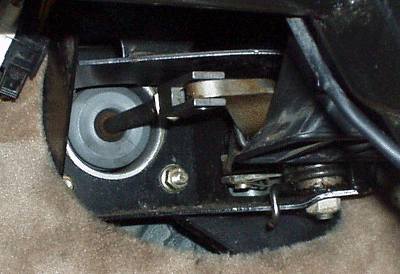
Note: my E32 is RHD, so this is the push rod/lever system, not the pedal end!!)
10) Remove the booster mounting nuts: use a magnetic pickup if you loose one of the top ones.
11) Put rags under the MC/booster under the hood
12) Get as much brake fluid out of the MC as you can.
13) Trace the two output brake lines from the MC down to the ABS controller/pump. Loosen their collar nuts. Don’t remove yet.
14) Undo the fuel line support bracket from the master cylinder mounting stud, and move the fuel lines out of the way. I hooked them behind the transmission dipstick tube.
15) Loosen off the pressure feed line to the brake booster, and the low pressure return line. Cover with a rag, & remove.
DO NOT let the low pressure line droop down, it will start a siphon of ATF from the fluid reservoir.
16) Remove the pressure feed line.
17) Undo the two brake lines into the ABS modulator; have a rag & brake cleaner/de-greaser ready, you don’t want fluid on the paint if possible.
18) You’re now going to try to remove the following assembly:
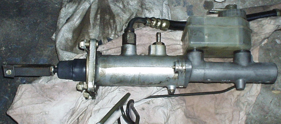
As you can see, the steel brake lines will need to be bent to get the booster clear of the hole in the firewall.
I suppose you could separate the master cylinder and the booster, but I took them out together.
Also take care with the brake lines, since they can be “folded” back on themselves, and also clipped to the lines going from the ABS modulator . . .
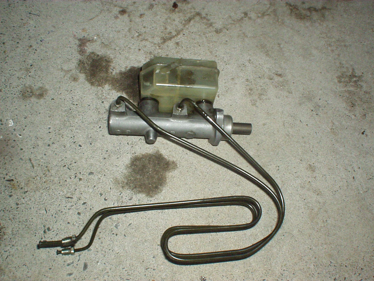
Here’s mine straightened out again:
19) Once the unit is out, put a CLEAN rag over the feed holes into the ABS modulator. You DO NOT want any grit getting into there.
20) Now – to get the new booster in! If handling the old booster from now on, (a) drain all the ATF from it and (b) likewise, drain all the remaining brake fluid too.
Pumping the push rod will help.
21) First, check your old booster against the new vacuum booster – the length of the push rod (pedal) shafts should be nearly identical, measuring from the mounting face (where it bolts up against the firewall) to the center-line of the push rod-pin hole. You can adjust if needs be.
22) Now separate your booster from the new master cylinder. It doesn’t matter that the new cylinder looks shorter than the old one, as you’ll now see – the vacuum booster contains the last 2″ or so of the new MC.
23) Try fitting up your new booster without the new MC and see what needs removing to get clear access. I had to remove the throttle/cruise control cables, the engine wiring loom connector (the big 2″ round one, undo its cover then TWIST the ring around the plug to separate) and some other minor trim to get the booster even near to fitting in. I also had to bend the remaining brake lines (output lines to the 4 calipers from the ABS modulator) down to get them to allow the booster “donut” to fit in; on my car, they were “folded” like the old MC lines in the pic above. NB: my car does not have an auxiliary heater pump, so you may have to take care clearing this as well.
Be careful of the battery feed wires to the jump start post: you don’t want to damage their insulation.
24) Once your booster is in (make sure the vacuum inlet port is closest to the engine manifold!) you can tighten its four nuts from inside the cabin (22Nm torque) and reinsert the push rod pin (I greased mine a little before doing so: it may never get it again). Slide the clip back on the side you found it and CHECK that it’s engaged and you can’t lose that pin!! (Theoretically you’re finished inside the cabin, so if you’ve got assistance, they can reassemble while you fight on under the hood…)
Here’s roughly what it should look like:
Notice the ABS output lines compacted down – this is OK, as long as the bends aren’t really tight in curvature (I’ve discovered that standard BMW spare brake line comes shipped STRAIGHT, so some bending is always expected… just don’t give anything metal fatigue!!).
Notice also I’ve moved one of the power steering hydraulics lines out of the way to get clear access to the whole area.
25) So now.. the new master cylinder.
Here it is, by itself . . .
There are two important things visible here: (a) the MC goes back into the booster quite a way – so clearance to FIT it is different from what it needs in-place; (b) the rear outlet is at an about 45 degree angle to the units center-line.
This complicates the tightening of the lines A LOT.
26) My first move was to fit the outlet lines from the new MC to the ABS modulator (after a very good clean with brake cleaner). Get their cap nuts done up very lightly BY HAND. ALWAYS do these brake line nuts by hand: you do not want to even CHANCE a crossed thread in the ABS modulator, and if they’re stiff, try wiggling the brake line itself – chances are, it’s not on-center line for the hole.
27) Now try fitting up the new MC:
You can see the two output lines waiting to be connected, and that I’ve had to disconnect one of the ABS modulator outlet lines to get the new MC in on-center. Also, before I fitted the new MC in, I coated the face that mates with the booster with some brake-seal lubricant – it does have a seal, presumably for vacuum, so it’s worth the precaution.
28) Get the new MC into place on the booster, tighten nuts to 21Nm ONLY – tighter can damage that seal! You’ll need to take one off again later to refit the fuel lines clamp, but for now, get it fitted up properly.
Check from the cabin the pedal moves OK, but expect brake fluid from the MC so use rags first; we want to be sure the booster output push rod has mated with the new MC input shaft OK.
29) Reattach the output lines to the new MC. Tightness for me was a good pinch; remember, the seal is on the face of the flared end-section of the pipe, so extra tightness (beyond making the nut firmly secure) won’t improve the seal…
30) Tighten the still-slack other ends of the new MC output lines, at the ABS modulator.
31) Refit any other brake lines still off.
32) OK, summary of where we’re up to…
- Your booster is in, but has no boost as it’s not plumbed for vacuum yet
- Your new master cylinder is in, but it’s not filled and the whole system still needs a full brake bleed
- Your H31 system is out, but the pressure feed to the missing booster is still wide open – do not start your engine!!
My suggested course is to fix items 3 and then 2, and then you can at least (CAREFULLY) test drive the new MC before you take a drill to your engine. So… on we go.
33) On your old H31 booster, remove the thick pressure feed hose, and then check that the end that went into the booster fits the regulator as well. If so, undo the adapter from the H31 booster – this thing:
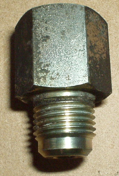
(Really only about 1″ long – macro mode gone mad, sorry)
What do you want that thing for? It’s internal thread is the same as the outlet on the regulator you want to block off : take it to a good car parts store and get an engine sump-plug that fits it – this will be your blanking plug. Mine had a magnet glued in; I snapped it off & filed off the “stump”, then ran it in and out of the adapter threads a couple of times, then applied teflon thread-sealing tape (it will have to cope with 850 PSI or so) and screwed it into the regulator TIGHT.
WARNING: This is an ongoing safety risk if anyone should dismantle the brake bomb and/or regulator. With the regulator output blanked off, there’s no simple way of depressurizing the brake bomb. I’m assuming that if work is required I’ll be undoing this blanking plug VERY SLOWLY, about 3-4 turns initially and letting the pressure weep out overnight. Longer term, I should really ditch the regulator, but the lines to the steering box – what I’d have to get to for the switch – are under the engine…
34) Using a handy bolt (I used one of the old Master cylinder to H31 booster bolts) and lots of the teflon tape, make a plug for the low-pressure H31 return line. As I wasn’t going back, I cut my line off to lie under the regulator bracket, out of sight. Secure the bolt with a hose clip.
35) Refit the majority of the engine bay items shifted/removed for access… you only need access to the brake fluid bottle cap and vacuum lines area now. You should rework the bracket for the fuel lines to fit the new MC bolt positions – I just filed the little locking flange off.
36) Make sure any disturbed power steering lines are reconnected, tight and not likely to transmit vibration. Make sure the clips to hold the cruise control/ throttle cables are fitted (or the two are cable-tied together). Make sure the battery feed wire (to the jump start post) is clear.
37) OK – it should now be safe to start your engine… you want to check for leaks on that blanking plug.
Expect the “BRAKE FLUID LOW” warning! Theoretically at this point you can still revert to an H31 system, but be aware again of the issues with undoing that blanking plug once there’s pressure behind it!
38) No leaks? Good. Switch off, and enjoy your time bleeding your brakes!
Remember:
- Right rear, left rear, right front, left front.
- Allow for plenty of pumping, you’re re-priming the ABS modulator too, remember.
- Keep the fluid level HIGH – at least at the very start.
- The fluid tank is 2 chambered, and so you need it high enough to be topping up both chambers, not just the front one.
- Look in the cap without the little “tub” in place: you’ll see the wall & entrance to the back chamber.
39) OK, theoretically you can do an optional step here – test drive the brakes WITHOUT the boost. Be warned – it’s like having to push your foot through the floor to get a very weak response… you remember what the resistance got like when you pressured-down the brake bomb, right? However, it does test for brake fluid leaks across all those lines you’ve disturbed. Just be very careful and (a) don’t go above 25Mph/40Kmh (my recommendation); (b) allow 10 times the usual stopping distance (c) try to do it somewhere secluded. I live in a cul-de-sac; lots of loops done later at night.
40) Now the brave steps. Take your vacuum hoses and dummy up the non-return valve (little arrow on the body goes TOWARDS the engine) and the brass hose connector – are they OK? Be careful with the standard BMW fabric-covered hose – again, the fabric contains 3 spiraled wires, very sharp to fingers!
41) If the hoses are all OK, find the tap that suits your brass hose connectors’ thread – check it by “chasing the thread” with the die that matches the tap. Find the drill bit required by the tap; pray to your chosen god, approach your car and drill a pilot hole and then the full-size hole in your intake manifold, ready for tapping.
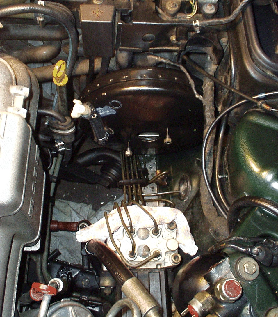
The location & end result is this:
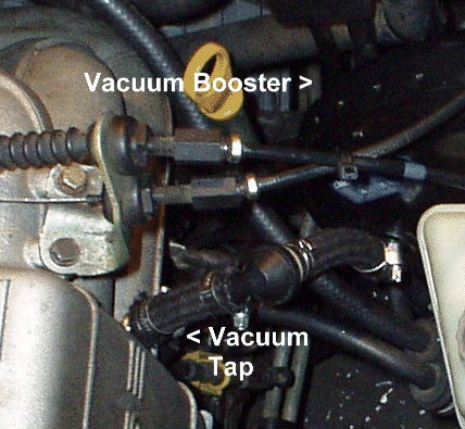
I know some of you will be cringing about now, but I wasn’t going to pay the wrecker for a “core unit” of a complete head/manifold just to get the precast vacuum tap… Back to practical matters, using a speed controlled drill with a new HSS bit meant I could use only as many RPMs as required, and so keep most of the drill swarf from going into the manifold. On finishing drilling, I used a focused-beam, fine work torch to see into the hole, and a Q-tip with a “dob” of Vaseline on it to “dab” up the little metal that did go in; I repeated this after tapping the hole as well, spending a good hour making sure there was no debris left. The fitting of the brass hose adapter was as normal, but with some teflon thread sealer tape for luck too.
42) Now, assemble your vacuum hose setup, and hose-clamp as required.
43) Start your engine; there should be no change in engine behavior. Try the brake pedal; you will notice a faint hiss as the vacuum is released by taking air in around the pedal push rod shaft (yes, there is a filter there!). Pedal action should be as good as with your old H31 setup.
44) Test drive. Since you’ve disconnected the battery, take it gently while the gearbox re-learns it’s pressure presets.
So . . . that’s it. The brakes seem to be a little more progressive now, I think I’m using less force to stop creeping in traffic queues, and the pedal doesn’t “sink down” when held on for a long time.
I can’t get the ABS to “fire” on practice emergency stops (on asphalt) anymore, but I think this was actually a problem with the old system anyway.
It really seemed to “bite in” at the very end, and the ABS having to modulate out a skid seems to bear this out.
The new brakes seem much more progressive, and stopping distance hasn’t increased, and I don’t need help from the ABS on a dry stop anymore…