Article by: Max Fretter, updated and edited by Mike Oswald
Applies to: all e32 and e34 models.
Both e32 and e34 owners either know about these things already, and have had them fixed, or need to know about them – that’s what this page is for.
The LKM or “Licht Kontroll Modul”, is the light control module, most important for switching on the headlights.
When it goes on the fritz, the main symptom is the lights becoming intermittent OFTEN WHILE DRIVING.
A tap to the fuse box sometimes fixes it, but not for long and then the “outages” become worse. Dealer response seems to be replace, but these units are expensive (approx $400 US each) . . .
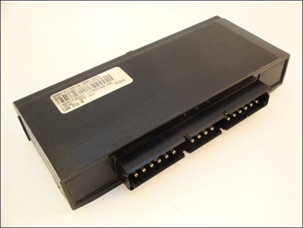
The LKM unit is easy to get at as it simply pulls out:
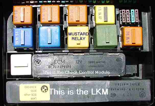
The LKM is similar but a more complex beast than the “mustard relay”. For additional information on how to repair the mustard relay click here.
The LKM also has components sensitive to static electricity in it, so some handling care is required.
I’m saying this up-front as then you know it’s a slightly more advanced project, but only to follow more instructions, really.
The module changed internal construction around 1992 from the one presented here – this is my 1987 one.
The part below about finding & re-soldering the contacts for the relays still applies.
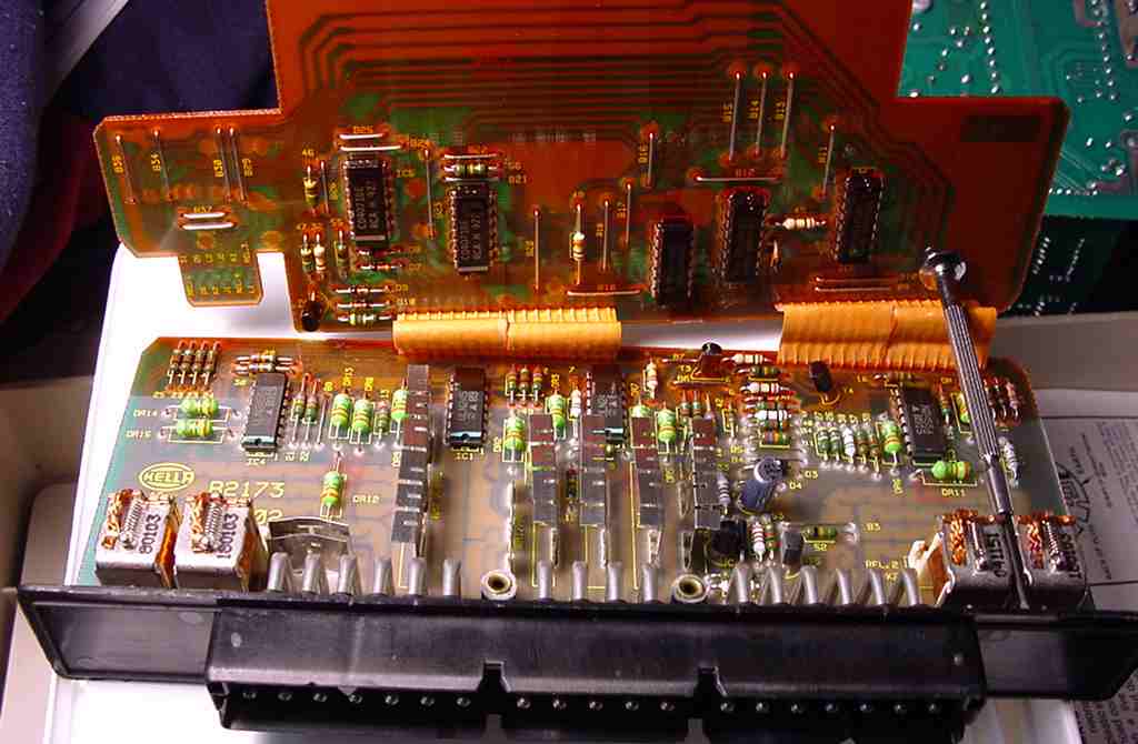
Here’s what it looks like inside so you can get an idea – remember, you’re still only re-soldering the relay solder pads . . .
Notice that there are several versions of the LKM with very different circuitry configurations:
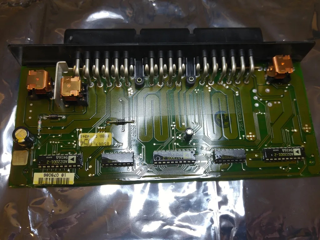
Notice the relays? One for lows, one for highs, one for fogs each side . . .
OK, you need your soldering gear again, but also a nice sharp screwdriver.
You open the case from the bottom – there are four barbs that overlap the bottom plate from the “can” body.
Pry them out of the way (some people report good use of old credit cards or similar stiff plastic sheets for this) then the boards slide out.
The integrated circuits on the boards appear to be the static sensitive CMOS types, but Hella have painted all the parts with an insulating varnish so they should be OK for some light handling.
Basically, try to handle by the edges of the PCB or the connector block when you can… there is no meed to touch the chips here anyway.
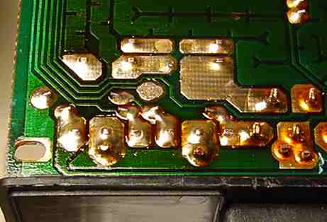
OK, now turn over the unit to see the bottom of the main circuit board (attached to the main connector).
What you have to fix is the relay soldering in either bottom corner, for the main relays.
Here they are in all their glory, the ones on my LKM anyway . . .
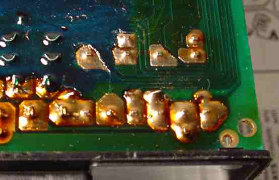
The one above shows how you may need to scrape back the varnish that has been painted over the board underside to get the joints clean for re-soldering.
When finish, again, carefully reassemble (make sure the two boards engage in the two slots in the case) and reinstall.
Test your lights – hopefully the intermittent operation is a fading memory . . .