Article by: Sean
Article applies to: all models with the M70 V12 engine.
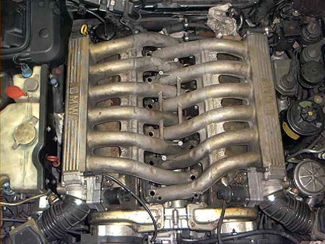
Problem: The last couple of months my V12 developed a rough idle. These engines can run like sewing machines, but not in my case. More like a 2-stroke chainsaw…first I looked for the obvious problems.
Vacuum hoses, bad ignition wires, bad spark plugs….you name it, but I couldn’t find the real source of the problem. Changing the ignition wires seemed to help a bit, but I still didn’t have that smooth idle.
Glad I didn’t spend 600.00 Euro/US dollar for a complete new spark plug wire set….
At a Saturday afternoon, I decided once more to search for the problem, but with a different approach.
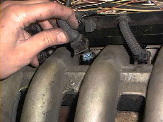
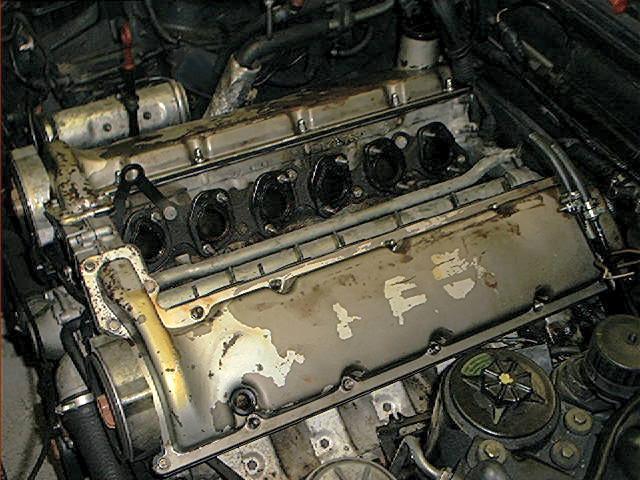
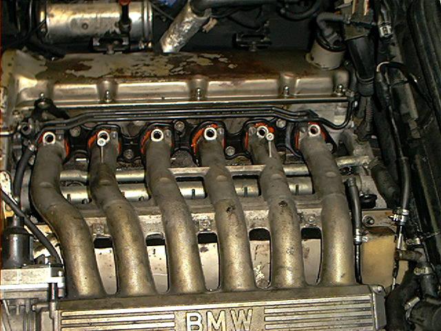
I removed the plastic engine cover that covers the fuel injectors and I disconnected the 6 injectors of the left bank:
After this, I started the engine. The engine should run on 6 cylinders almost even smooth when running on 12 cylinders (unbelievable, but true). I repeated the procedure at the other bank and noticed a big difference between the left bank and the right bank. The left bank was running smoothly and no vibration whatsoever, and the right bank was stumbling and hesitating. Now I knew which bank caused the problem.
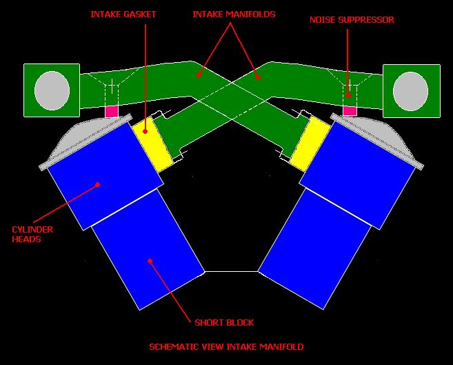
Engine running only with the hesitating bank, trying to investigate where the problem lies, I leaned forward with my elbows at the top of the left intake manifold (which is connected to the right bank, still getting it?). At a sudden the engine was running even worse. I wiggled the manifold slightly up and down, and the engine almost stalled. Right. This one is gonna cost some serious bucks. I was already afraid of this one: the infamous intake manifold gaskets where leaking….aaarrrggghhhh.
These intake gaskets are expensive. Very expensive. I mean really expensive. You’ll gasp for air when you are laying on the floor before the counter of the local BMW dealer. We are talking about a stunning 100.00 Euro/US dollar for each gasket. And you need 4 of them.
At that particular Saturday afternoon, that wasn’t simply the solution for the problem. The local dealer was already closed (and most likely he had to order the parts because they where not in stock), my wallet was empty due to the formerly replaced front wheel bearing and spark plug wire set, and the car must run at Monday because I had to go to my work (to earn the money needed for the parts to keep my car running…..what a life).
Decision: to quickly remove the left intake and put some sealant between the intake manifold and intake gasket, reinstall everything and hoping the leak isn’t between the gasket and the cylinder head.
This was added at Feb 2005: this turned out to be a bad decision after all. Later on, I did both manifolds and also resealed the surfaces between the gaskets and the cylinder heads. I added this procedure to this story. This was a better solution.
Background: The large intake manifolds gaskets aren’t the usual, paper thin gaskets. These are thick ‘rubber’ gaskets, with a nasty tendency to shrink over the years, causing vacuum leaks and poor idle. Someone else reported that the gaskets are thick because it prevents transferring heat from the cylinder head to the intake manifolds. Nevertheless, its probably a bad design, virtually every produced V12 has had this problem or will suffer from it in the nearby future.
Lets start unbolting things:
REMARK! The photos are showing that the black plastic cover that protects the complete injection harness is removed, exposing the complete wiring of the injectors, engine sensors and DK’s. You don’t have to remove this cover.
I removed it due to some changes/experiments with the injection system. You can lift the entire harness, stuck between the fuel rails, up and set aside.
Also, you DON’T have to remove the DK motor (throttle body), instead of what the Bentley Book and the factory manual are saying. Keep it attached to the manifold.
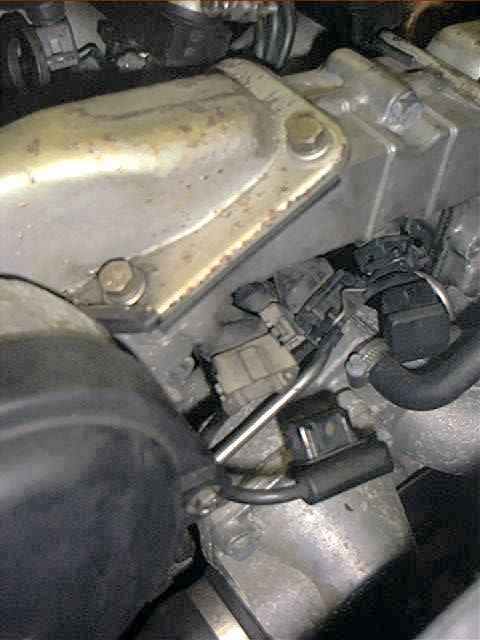
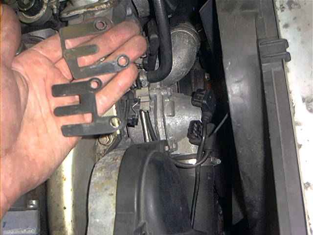
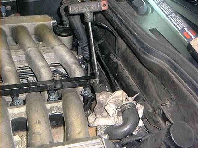
After removing the plastic engine cover and removing the coolant expansion tank, remove the brackets above the injector harness:
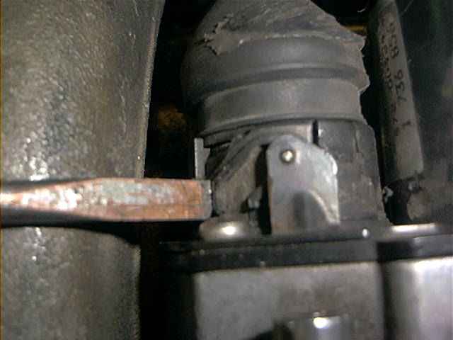
Disconnect every injector connector, use a flat-blade screw driver to push the retainer clip up:
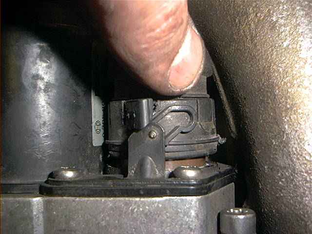
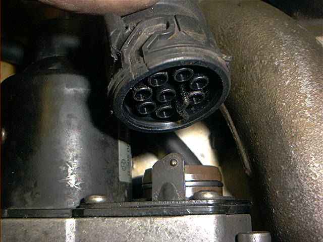
Disconnect both DK motors, sometimes a screwdriver is necessary (a piece from the connector disappeared):
Remove the cylinder identification sensors and crankshaft positioning sensors at the front of the engine:
Remove the clamps that hold the connectors:
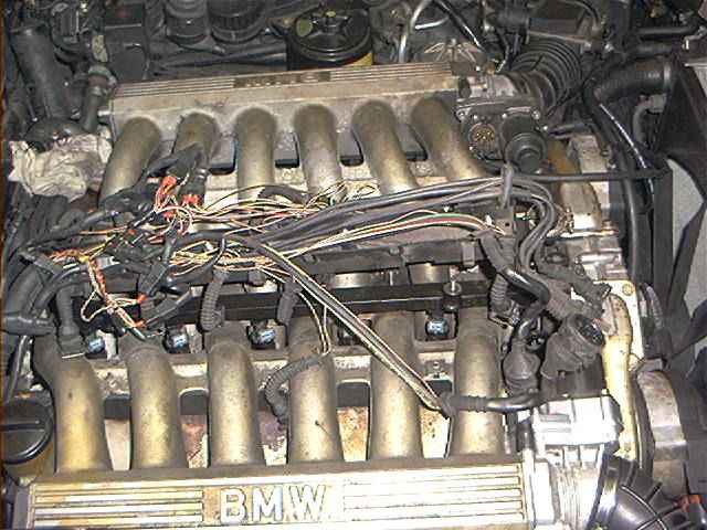
Now lift the entire harness up (don’t get scared of this picture and read the remark at the begin of this section, you can leave the black plastic cover onto the wiring harness.
I made some modifications and didn’t reinstall it, ending up with this myriad of wires) and set aside:
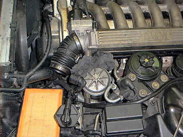
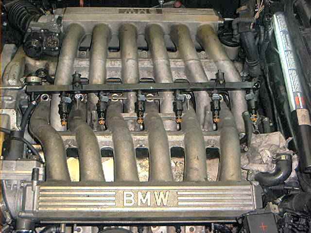
Remove the air mass meter and crankcase vent hoses:
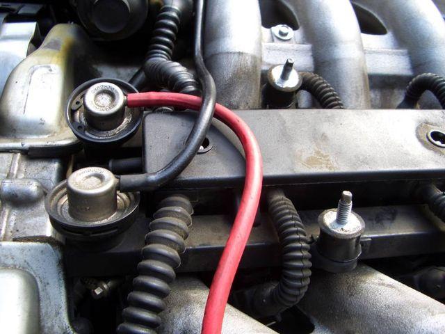
Detach the vacuum hoses of both fuel pressure regulators: (take note that the vacuum lines go to the regulator on the opposite banks!).
Loosen fuel hose clamps (2 supply hoses, 2 return ending up in 1):
Remove the Allen bolts of the fuel rails (one rail is already removed to make things more visible for the photo):
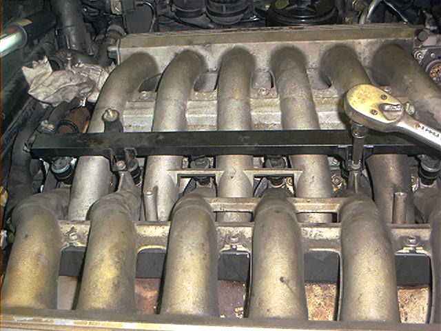
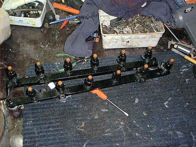
And remove entire rail with injectors (pull it gently straight up):
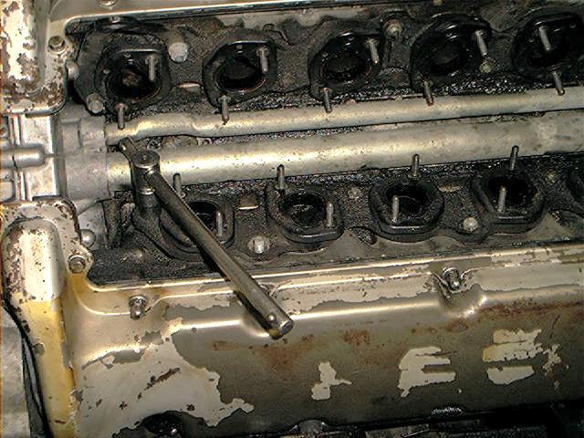
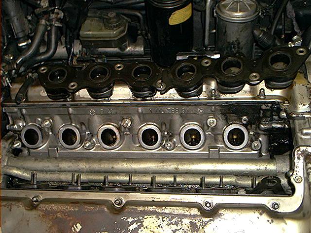
When both rails are removed, it should give a nice picture like this:
My 12 injectors looked like this:
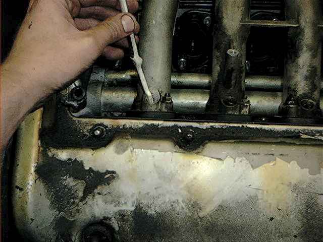
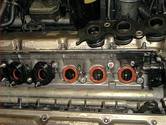
I also cleaned the injector holes (bores) with the same solvent and an old toothbrush (intake manifold removed to clarify the process):
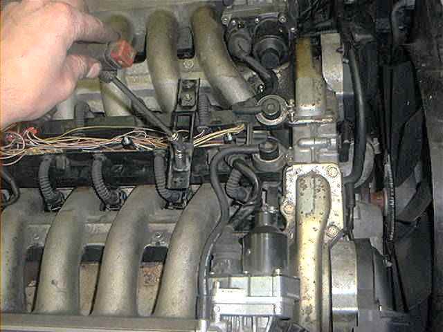
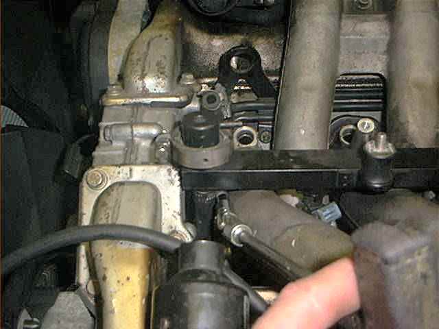
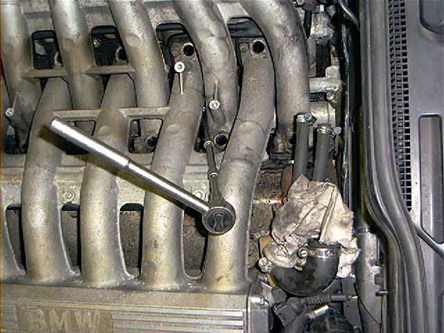
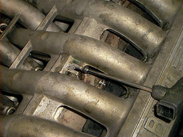
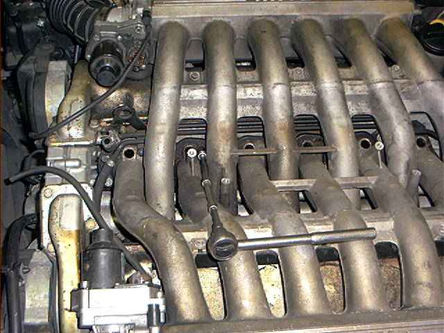
Now comes the tricky part, unbolting the lower bolts of the intake manifold. The trick is to use a 10mm 1/4″ socket with a 1/4” swivel and alot of extensions.
I used a 3/8″ ratchet with a 1/4″-3/8″ adapter to apply more torque:
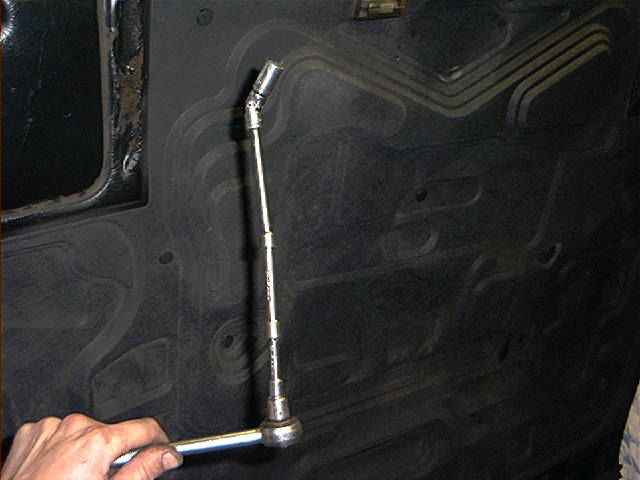
For the lower bolts the 10mm socket must be magnetic to prevent the bolts falling into the valley between both banks (pretty important when reinstalling).
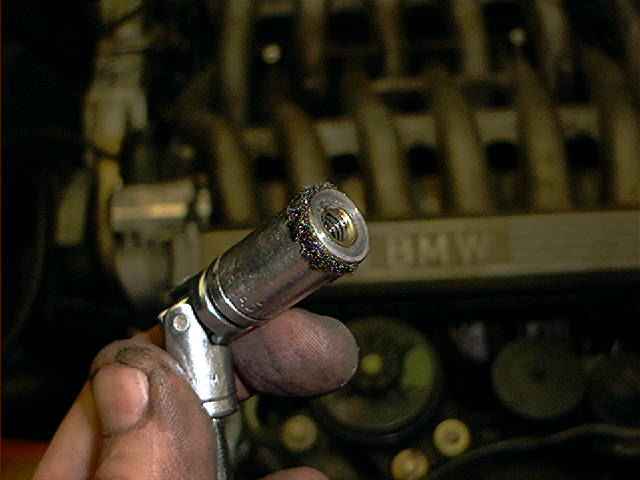
I can assure you, no one I know has magnetic sockets. Neither do I, so I used an old trick. Put some wheel bearing grease into the socket (its a bit out of focus, but you’ll get the point):
I also greased up the swivel, to make it less flexible. A swivel that swivels to smoothly causes severe headache when you are trying to reach those bolts:
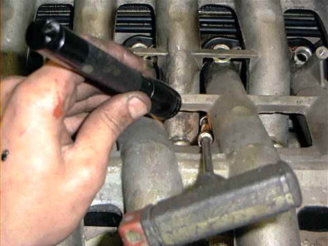
Next pictures are showing the removal of the lower bolts.
REMARK: the photos are showing that my ratchet and extensions use the small space between both manifolds.
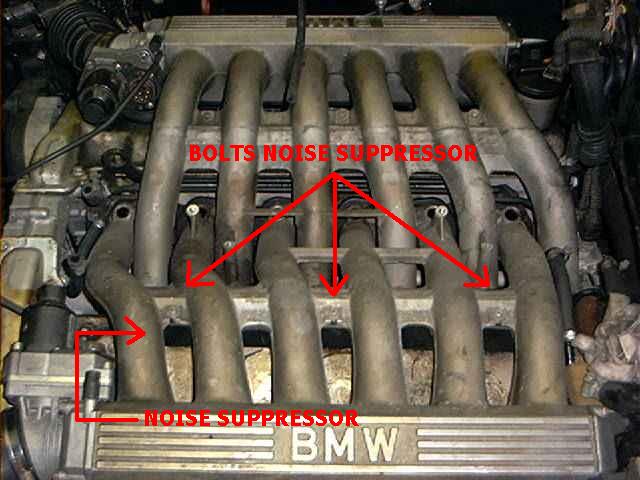
For easier access, you could remove the bolts of the noise suppressor (see schematic overview at the beginning of this article) and move the noise suppressor to the back of manifold, allowing a better access to the lower bolts.
I described that procedure in the ‘valve stem seal replacement’ section.
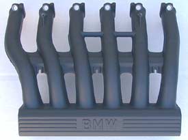
The noise suppressor is nothing but a piece of plastic with some isolation, together with the engine cover it prevents noise from the injectors:
Again, I didn’t remove the noise suppressor, notice the lack of space you have. No space for anything bigger than a 1/4″ swivel. Time to start unbolting.
I started at 2 bolts near the firewall, which in my opinion where the worst to get at:
Later (see second part at the end of this section) I did remove the intake manifolds for the second time, and this time I removed the noise suppressor. Access was a lot easier now, and without swivels:
It’s up to you which procedure you use. See section ‘valve stem seal replacement’ for more pictures about this procedure.
The bolts where sometimes very hard to see. I used a small electric flashlight:
A removed bolt, nicely sticking to the grease 😉 :
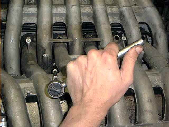
When all lower bolts are removed, pass on with the upper bolts, which are relatively easy:
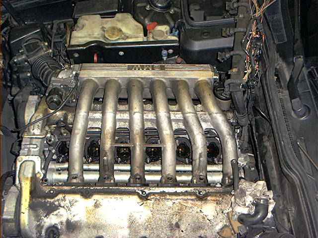
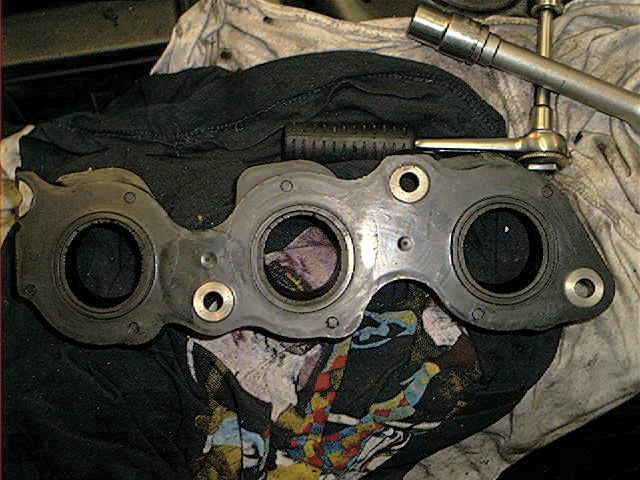
When all bolts are removed, detach the left intake manifold from the cylinder head. Notice the intake gaskets. On the photo it looks like 6 separate gaskets, but they aren’t.
These are 2 massive gaskets, bolted with other bolts (not the bolts you removed!) to the cylinder head. Therefore, you can’t remove these gaskets now, you have to remove the other manifold for that.
When replacing the gaskets (which I didn’t), just must replace both gaskets and you cannot replace the gaskets of 1 bank only….it always requires to remove both manifolds:
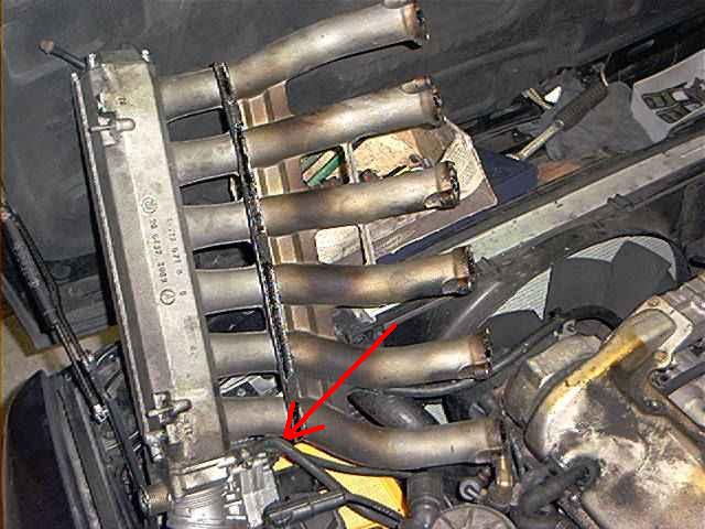
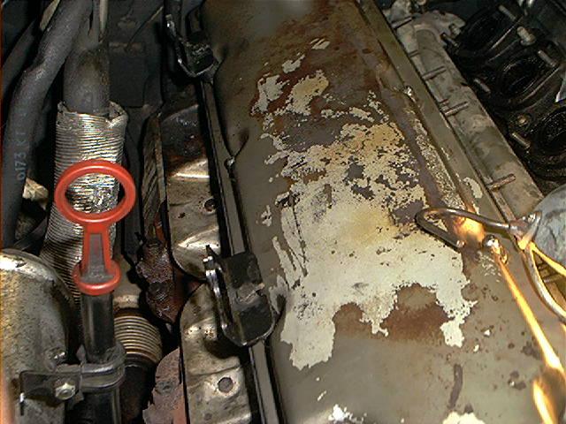
Here you see the bottom of the intake manifold. Notice the attached DK motor. The black trim is the noise suppressor.
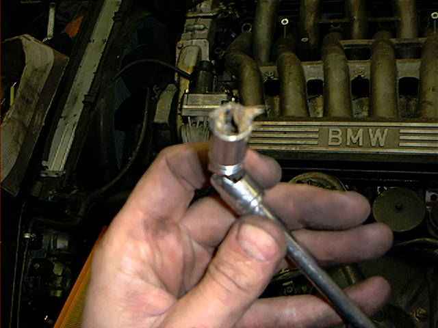
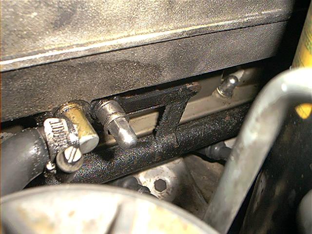
The arrow is showing the connection hose of the fuel evaporative vent system. The hose is going from the intake manifold to the evaporative purge valve.
This hose can’t be disconnected with the manifold installed (unless you are detaching the DK motor), so may be its a good time to replace it now while your at it.
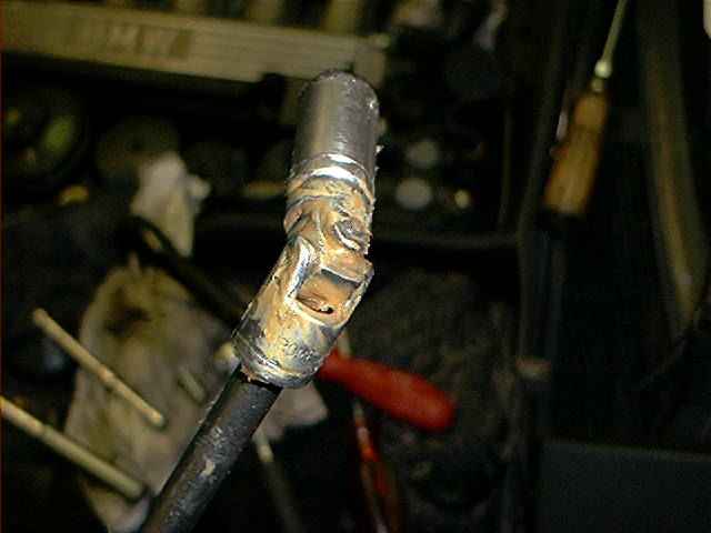
In my case the hose was hardened, cracked and brittle. You can use any ordinary 8mm fuel hose for this:
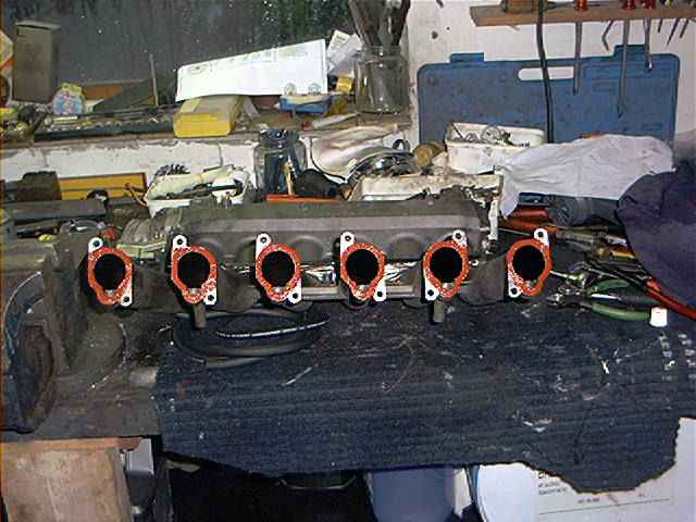
After cleaning things up and de-greasing the connecting surfaces (the gaskets and the intake manifold) I put some sealant on the surfaces.
Don’t overdo this. It looks like a heavy coat of sealant, but it isn’t. Just a thin layer. My workbench is a bit messy here but it was getting late and I was in a real hurry . . .
This part was added later, at February 2005: later on, I developed again false air problems.
When replacing my valve stem seals, I decided to remove every intake gasket (because both manifolds are removed anyway) to reseal them with sealant. I took some pictures while doing that.
Both intakes removed:
Removing the intake gaskets, just a couple of 13mm nuts:
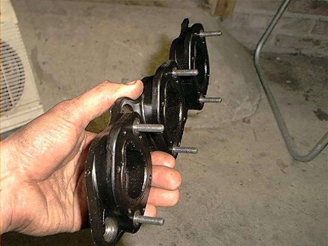
Removed intake gaskets from one bank:
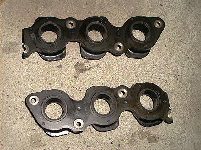
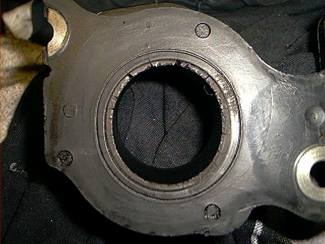
Notice how thick they are:
Cleaning the gaskets. These are still the original ones from ’87 (build date Nov 1987 model year 1988):
Notice the cracks. Normally this is a good reason to replace them, but I assumed the sealant will do its job properly:
Cleaning and de-greasing the surfaces of the intake ports, gaskets laying on top of the valve cover:
Applying sealant, one intake gasket already installed:
And installing the manifold. I used a little to much sealant..hmm…:
That was about it. After this I reinstalled the manifolds. Don’t over tighten those manifold bolts, it isn’t necessary. Just 10 NM (7 ft-lb) will do.
Start in the middle and work your way round. Use grease again for the socket, to prevent those bolts falling out when installing.
Furthermore, the re-installation is pretty much the reversal of removal.
There has to be a reason why even new intake gaskets seem to fail again over a certain period of time.
I think it has something to do with the manifold support brackets mounted onto the valve cover, as shown here:
Just make sure the brackets are in place, the rubber mount is still in one piece and that the manifold is bolted tight to the brackets.
A lot of people seem to remove the plastic ignition wire guides but if you don’t reinstall the small nuts of the guides, the manifold isn’t bolted to the brackets anymore…this put to much stress to the intake gaskets.
Make sure both brackets are securely mounted to the manifold.
The next picture shows the manifold tightened to a support bracket, without the ignition wire guides.
I used a thick washer between the bracket and the nut (remark: I got this washer from a set of discarded wire guides..they are simply to remove from the guides):
Total amount of parts and cost:
None. Just some sealant and a new purge valve hose.
Total amount of time:
At least a full day.
Skills needed/difficulty level:
Definitely good technical skills. Don’t drop the nuts into the valley.
Satisfactory level after the job done:
Smooth idle now. Don’t do just one manifold like I did the first time, but do them both and also seal the gaskets between the gasket and the cylinder head.