Article by: Sean
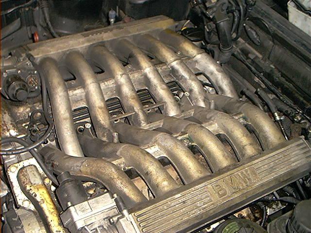
Article applies to: all models with the V12 M70 engine.
Problem: Smoking engine. At first I thought the massive oil consumption was also related to the worn valve stem seals, but later (after replacement of the seals) it proved I was wrong, at least in this case. Mine burned 1 liter of oil every 800 km, and it swallowed already about three 60L barrels of 10w-40 oil since I got it. An expensive problem, so it was worth the shot. But I wanted to decrease the blue smoke anyway. Some other people reported the replacement of the valve stem seals did affect oil consumption, so there are different experiences.
You can recognize worn valve stem seals by the following: let it idle for a couple of minutes with a warmed up engine. When pulling fast away, you’ll see embarrassing blue clouds behind you. I also noticed on mine that after a period of harsh decelerating (no smoke), putting your foot on the pedal made smoke.
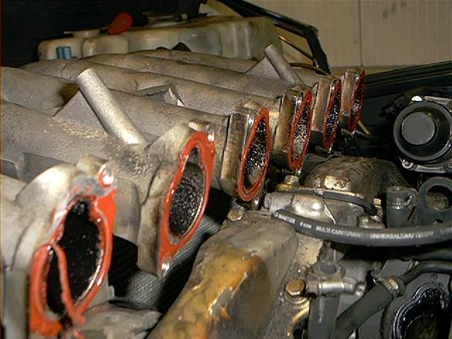
Another lead is to pull one intake manifold after 10 minutes of idling. At that point you’ll see the intake valves covered in oil.
Background: the valve stem seals prevents engine oil sucked past the valve guides. When the seals are worn, the high intake vacuum sucks the oil in. At that moment the oil ‘builds up’ on top of the valve. When you floor the pedal, the oil is sucked into the combustion chambers, causing the blue smoke.
My experience with other engines is that usually the spark plugs develop a high carbon buildup when the seals are worn. Not the v12, probably because the combustion process on these engines is just very, very efficient. The oil completely burns.
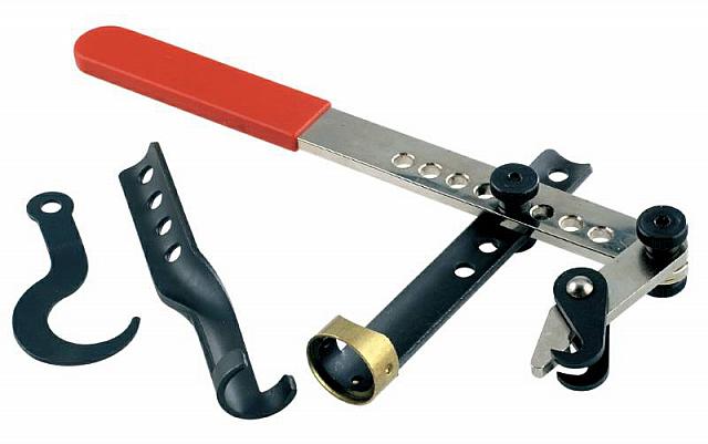
The nice thing about the v12 valve stem replacement is that you don’t have to pull the heads, even the camshafts doesn’t have to be removed. The downside is that you need special tools. You need a special tool to depress the valve springs (and no ordinary valve depress tool because you remove them with heads installed) and a special tool to pull the seals. I’ve used tool 13168 from Midlock (no aff.) to depress the valve springs and I made a special tool by myself (from old pliers) to pull the seals.
Now I thought Midlock tools where commonly available throughout the world, but that doesn’t seem the case. Perhaps in your country is some similar tool available or else, if enough interested people email me, I can contact the factory (it’s located in my country) so I can locally buy a couple of these tools and sell them (non-profit) to anyone who is interested.
However, there was a visitor of our site who created an ingenious valve depress tool by himself. Jaan about this:
‘Yes, we made the tool. We used J shaped pipe, 2 holes drilled into, as lever. One hole holds J shaped wire/rod (don’t know exact word, ~5 mm steel) that hooks to camshaft from below and another holds wire/rod (same 5mm) that pushes valve top.
Rocker can be removed when you push valve down enough (as I said before, you have to push on little round object between valve platter and rocker).
Seals were removed with pliers, you just have to wiggle, turn and pull, until it comes off.’
Keeping the valves up by compressed air is a possibility.
Another way is to remove the spark plug, put a couple of inches of some flexible rope into the cylinder (keep a loose end out of the spark plug gap) and slowly turn the engine so that the piston is pressing the rope together and keeping the valves up.
Let’s start unbolting and removing parts:
In the section ‘intake manifold’ I wrote an comprehensive article about R&R the intake manifolds, so I won’t get deep into this.
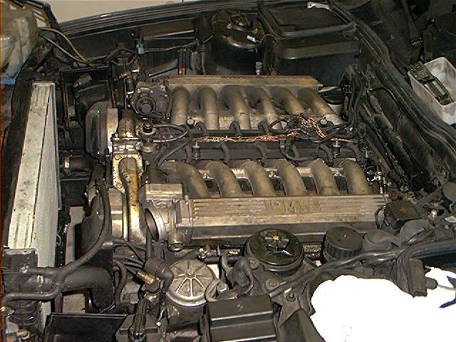
Removed the engine cover, upper air filter housing, MAF’s, visco fan (for easily turning the crankshaft) and intake boots:
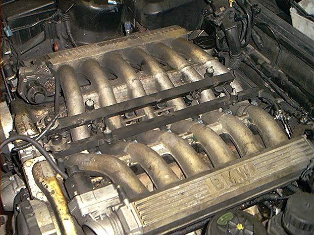
Remove engine harness, use a wire to keep it away (I put it underneath the windscreen wiper), remove vacuum hoses to fuel regulators:
Unscrew clamp hoses of fuel feed and return:
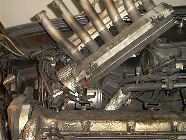
Unbolt fuel rails:
Pull rails up and remove them:
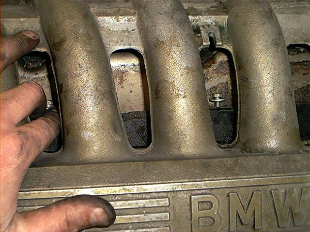
The difference with the story I wrote in ‘intake manifold’ is that this time I decided to remove the noise suppressors (located underneath the intake manifolds) for easier access of the manifold bolts.
This is because Frank Hoernlein reported to me:
‘Unfortunately you didn’t remove the noise suppressor when you wrote the intake manifold removal procedure. This because those BMW engineers designed something awesome to make this easier. When you do remove the noise suppressor first, you can easily reach those 10mm nuts with a socket and 1/4 extensions WITHOUT swivels. You can’t make a mistake, there is just one possibility to put the extensions through the gap between manifolds. When you pull the manifolds next time, try it. Simply brilliant.’
Always willing to learn something new so I tried this procedure.
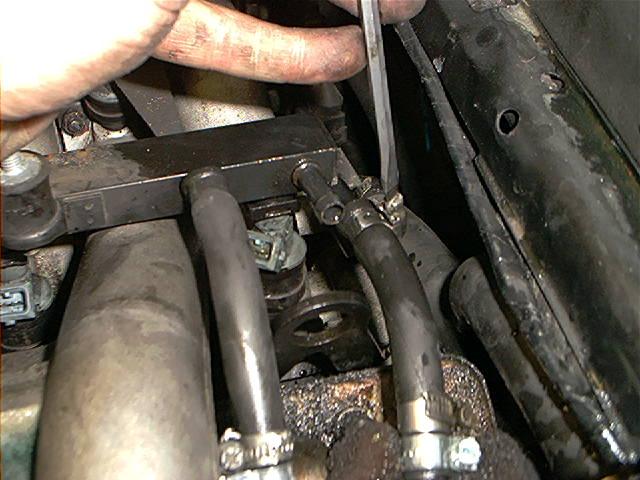
The noise suppressors are mounted with 3 tiny 7mm nuts:
It is virtually impossible to entirely remove the noise suppressor while the manifold is installed, so I moved it as far away as I possibly could:
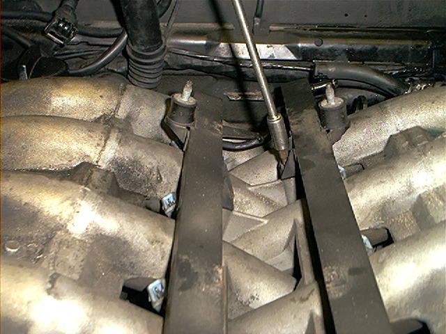
Ok, this was difficult to take. I tried to photograph a nut that is visible now:
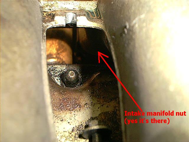
Frank was right at it. No swivels, just a 10mm socket and some 1/4″ extensions did the job.
One remark: this nice little trick only works if you remove the driverside manifold first:
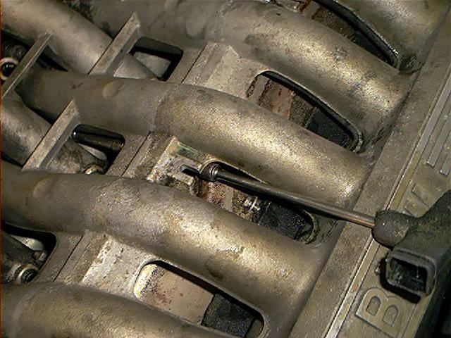
Some grease onto the 10mm socket helps preventing the nut falling into the gallery:
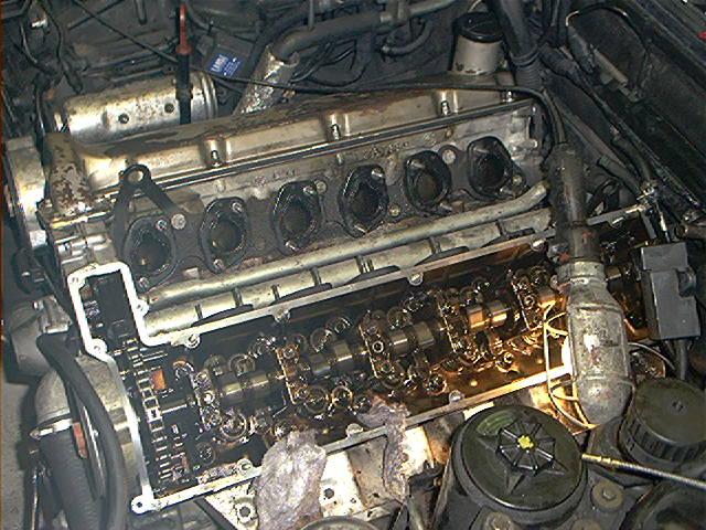
Left (driver side) manifold removed. Don’t forget to disconnect the vacuum hose underneath the throttle body.
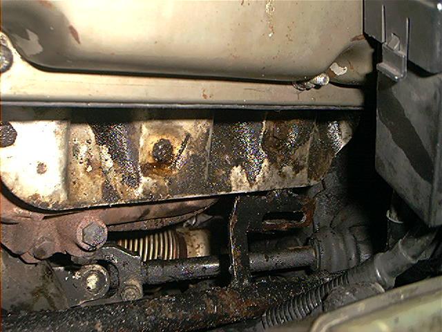
Notice the sealant used on the previous repair. The noise suppressor is still laying on top of the valve cover:
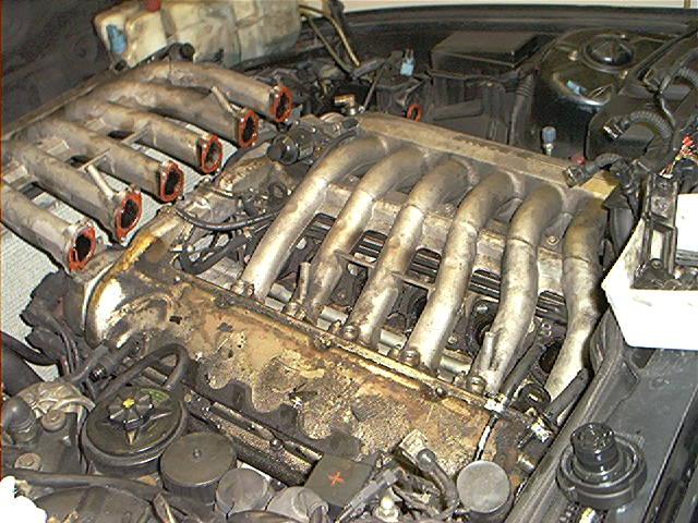
The downside of using sealant is that you have to clean the surfaces before you apply new sealant.
Be careful not to scratch the soft alloy when removing the remains of the old sealant.
Tip: a credit card proves very useful doing this (my flexible friend):
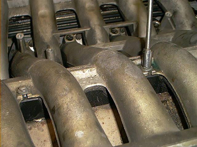
Unbolting the other manifold. You have very easy access to these bolts now. Notice I used a 1/4″-3/8″ adapter to apply more force:
So much for the right manifold. Check the vacuum hose underneath the throttle body while your at it.
Mine broke instantly into several pieces, completely brittle caused by expose of heat of many, many years:
Notice the amount of debris after years and years of driving. The fuel return lines are still installed but have to be removed:
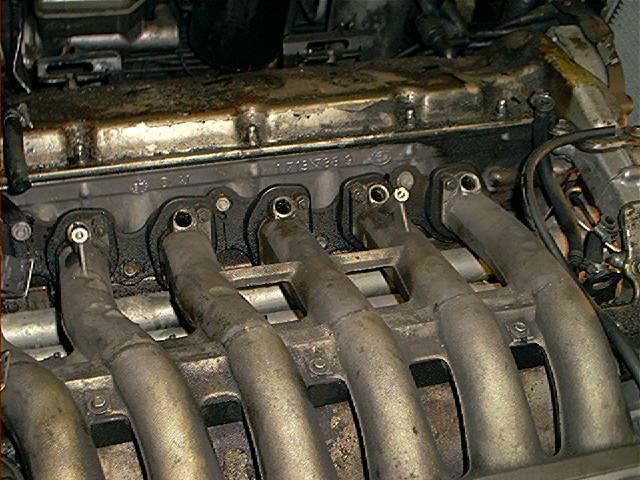
Removing the manifold support brackets and rubber mounts:
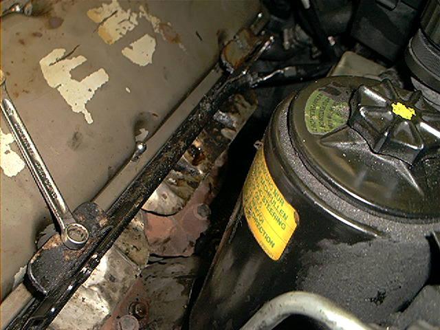
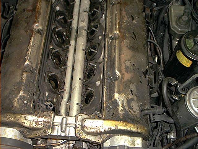
Unbolting the valve covers:
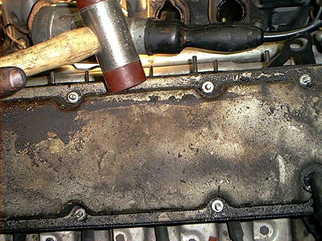
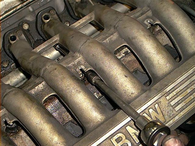
The valve covers can be a bit stubborn to remove, tapping with a soft hammer will help:
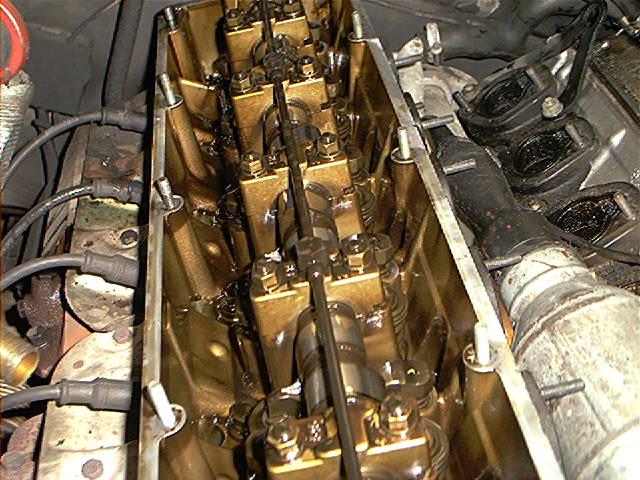
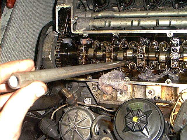
The valve train exposed. An experienced DIY’er or mechanic will see that this is a well maintained engine.
Use a synthetic or semi-synthetic oil from known manufacturers, change frequently and use good brand of filters and it will look like this (had to throw this in):
Before you proceed: there are 3 main things you have to check before you continue.
check if the oil banjo bolts of the oil spraying bar are loose
check carefully the lobes of the camshaft for wear and tear
check if every head bolt is secure in place. Do not tighten them, just check if they are perhaps broken(!)
Could you please reread the 3 items above? I cannot, repeat cannot emphasize how important this is.
The loose banjo bolts are a notorious problem, eventually causing insufficient oil supply to the camshaft(s). Horror of all horrors.
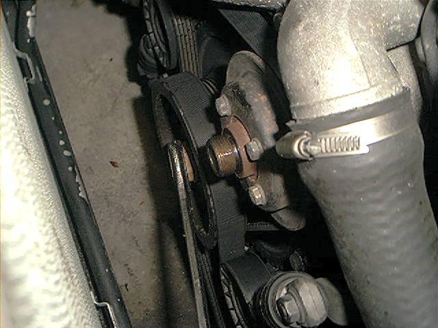
I suspected loose banjo bolts because when I looked at the oil supply of my camshaft with a removed filler cap and a running engine I didn’t see a nice stream of oil squirting onto the camshaft.
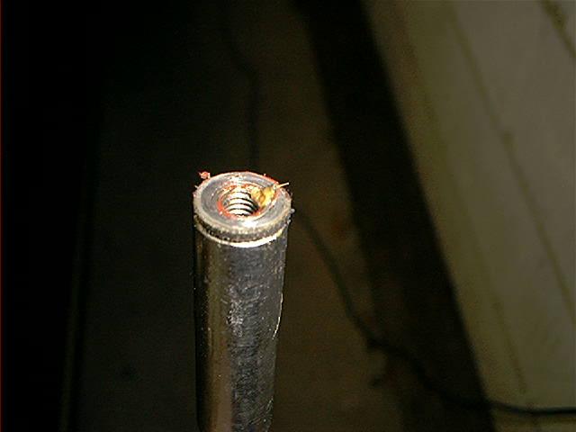
And I was right, 3 bolts where just finger tight:
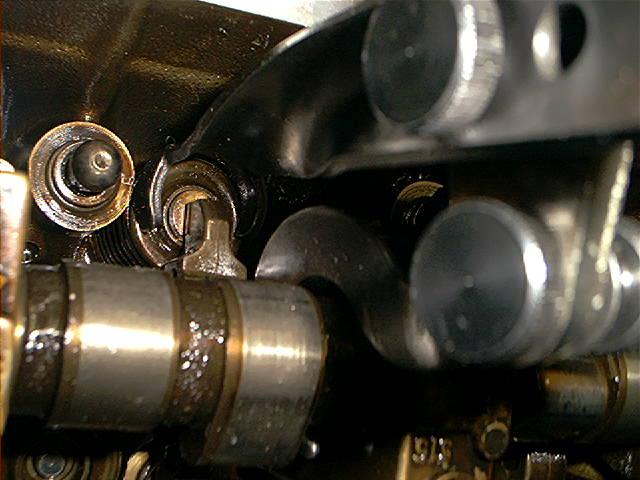
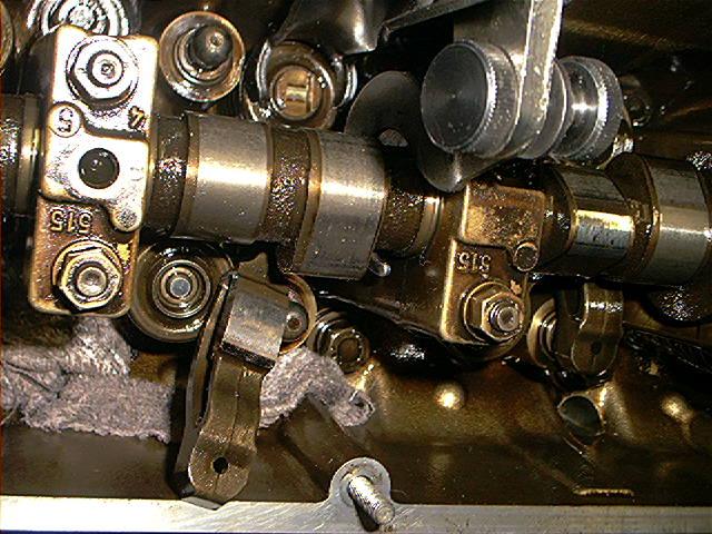
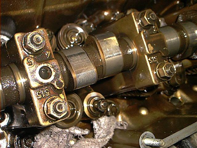
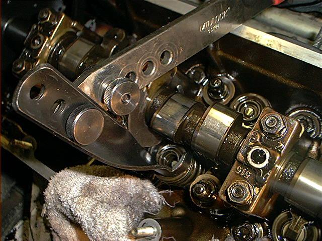
I removed the oil spraying bar and carefully checked every lobe of the camshaft (rocker arms removed for better understanding):
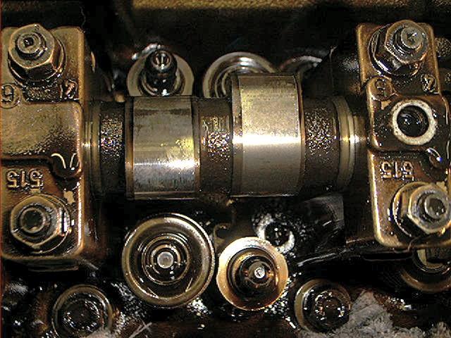
A nice looking camshaft after 440dkm/275Kmiles isn’t it? Most of the lobes where in pristine condition, some had a slight wear pattern. How to check?
Slide a finger nail across the highest lobe surface from one end to the other. Do this in both directions. A size difference will show up when the fingernail catches an edge.
If it doesn’t, then you’re probably good to go. If it does, your cams are worn.
Also, it’s a good idea to cover the oil return bores at the bottom of the head to prevent parts falling into the crankcase. Because they will:
Time to remove the spark plugs, if you haven’t done this already. I found it easier to remove also the spark plug wires along with the distributor cap, making less messy.
At this picture I used the original BMW spark plug removal tool.
I had a hard time removing the spark plugs (hadn’t replaced them the last 100dkm/60Kmiles…so much for the ‘well maintained’ story…) so I wrecked the tool.
El cheapo steel if you ask me:
I won’t show you my worn spark plugs because I am to embarrassed to show them. A true miracle the engine did run on them.
To give better understanding how the valve train is assembled, a picture:
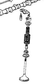
Now we can actually start with the replacement of the valve stem seals.
I did one cylinder at a time, because I don’t want to mix up parts (especially rockers arms needs to be installed at the same cam lobe position).
So I used the following procedure:
- Turn engine by hand until piston reached BDC (bottom dead center)
- Depress valve springs and remove rocker arms/rocker guides of one cylinder (pay attention cam lobes don’t depress a rocker arm)
- Put rope through spark plug gap
- Turn engine by hand until piston pushes rope against valves
- Depress valve springs and remove valve collets
- Carefully loosen tension and remove upper spring retainer, inner and outer springs. Don’t remove the lower spring retainers (not necessary).
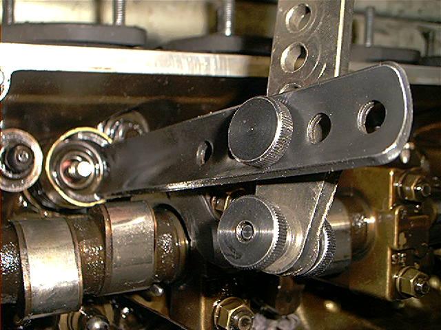
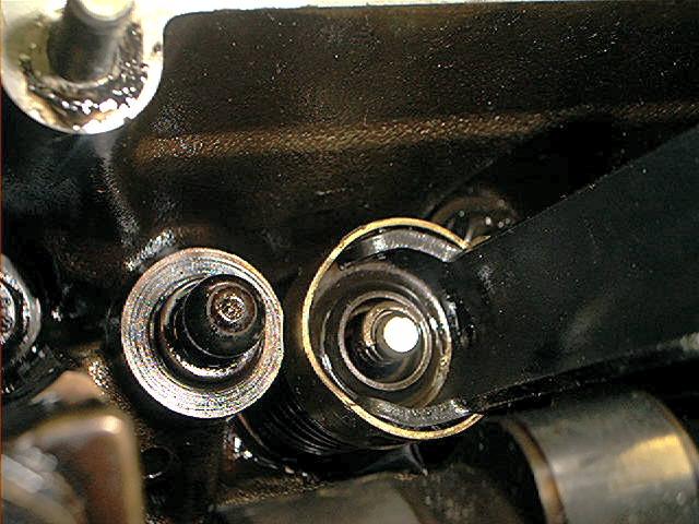
The following picture shows how I used the Midlock tool. Pay attention which setting I used so you won’t have to experiment which setting works the best:
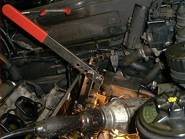
Sometimes you need to swap the hook and the ‘press bracket’. Notice that the hook is around the camshaft, notice the fact that is isn’t touching the surface of the lobe.
As said before, the first thing you have to do is remove the rocker arm. Turn engine by hand clockwise until the piston reaches BTC.
How do you know? Well, if both lobes are facing upwards or downwards the piston has reached TDC. After that, turn the crankshaft 180 degrees.
It should be in BDC now. Keep in mind that the lobe mustn’t depress the rocker arm or else you will have a hard time removing it.
It takes some experience to do this but by the time you reached the 12th cylinder, you are a pro. Believe me.
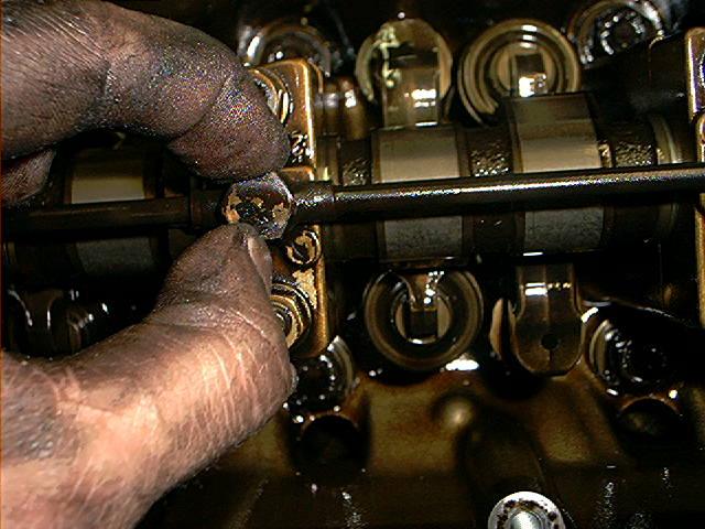
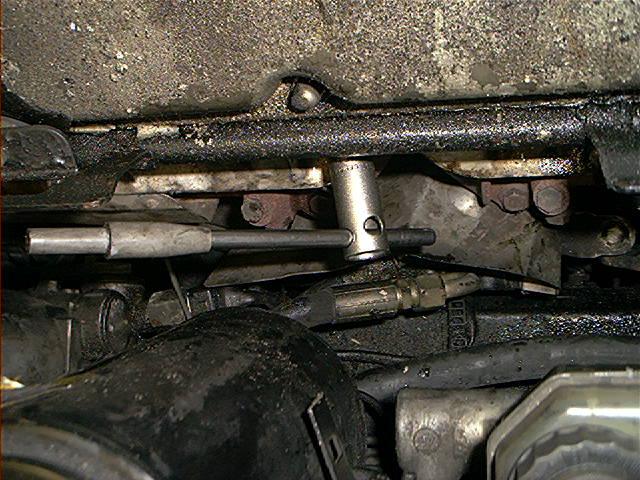
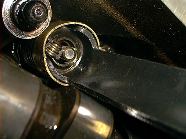
Depress valve. If you can’t depress it al the way down, try to turn the crankshaft a bit to see if it improves:
Slide rocker arm out between the lobes (there is no other way to do this so do this exactly like I show you, also the tool position):
Don’t forget to remove the valve guide on top of the upper spring retainer and think about a remark I made about covering the oil return bores.
*Please* do not forget to reinstall everything in their original position. Don’t mix up the rocker arms.
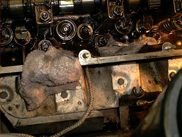
Now comes the hard part, keeping the valve up. Some guys are using compressed air and I guess that is the most convenient way. I did it somewhat different.
Get some flexible rope like this:
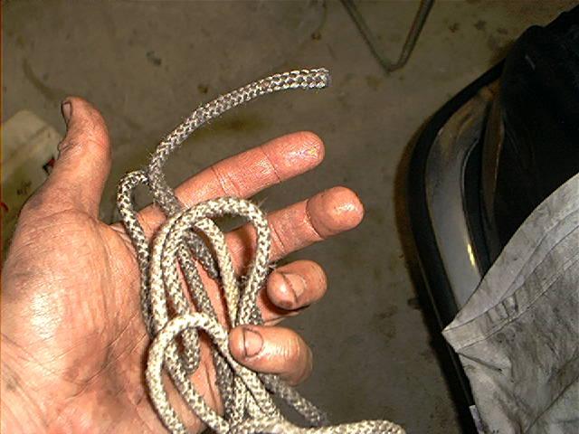
Put rope into combustion chamber through the spark plug hole:
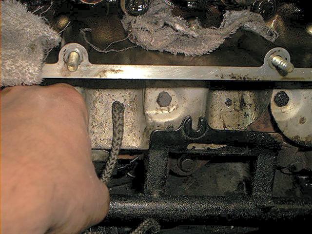
Put as much rope into the combustion chamber as you can.
I used some sort of plastic guide to make this easier:
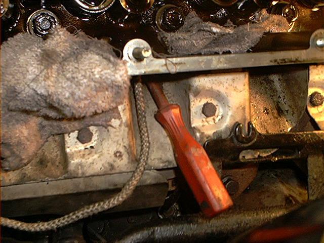
I don’t have to tell you to keep one side of the rope out.
If you are surprised and wondering why, ask yourself if you are up to do the job:
Now turn engine clockwise by hand until both lobes are facing up and you feel resistance.
If you don’t feel resistance and can turn the engine fully, you didn’t put enough rope into the combustion chamber, start all over again:
Check carefully if the valve doesn’t travel. Sometimes it can drop a bit before it pushes against the rope.
That can make the reinstalling process a bit difficult.
Notice I used another Midlock bracket for the next procedure (comes with the tool):
Depress upper spring retainer until you have enough clearance to remove the valve collets:
A magnetic pick up device proved extremely useful:
Carefully loosen the tension of the springs:
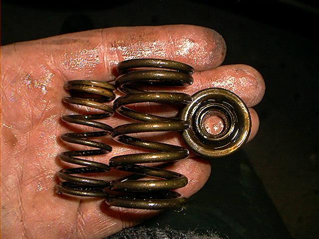
Now you can remove the upper spring retainer and inner/outer spring:
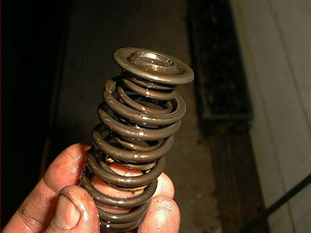
Now comes a tough part. Removing the valve stem seal.
From my experience, it’s almost impossible to remove it with a standard pair of pliers because you have to reach very deep and you have very little working space.
Midlock is also selling a expensive special tool to pull valve stem seals.
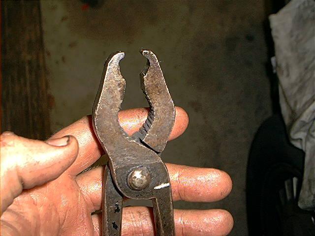
This was getting already expensive enough so I took an old pair of pliers and modified /ground it so I could get a grip onto the valve stem seals.
And another ‘special tool’ was added to my collection of tools:
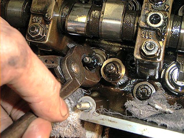
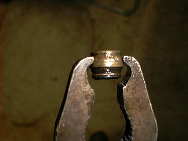
Carefully grab the valve stem seal beneath the outer ridge and start to pull, twist and turn. Pull firmly, don’t squeeze it:
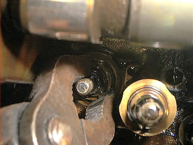
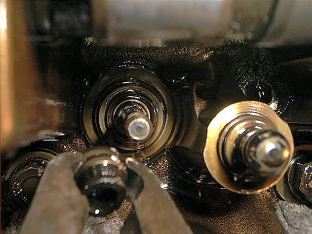
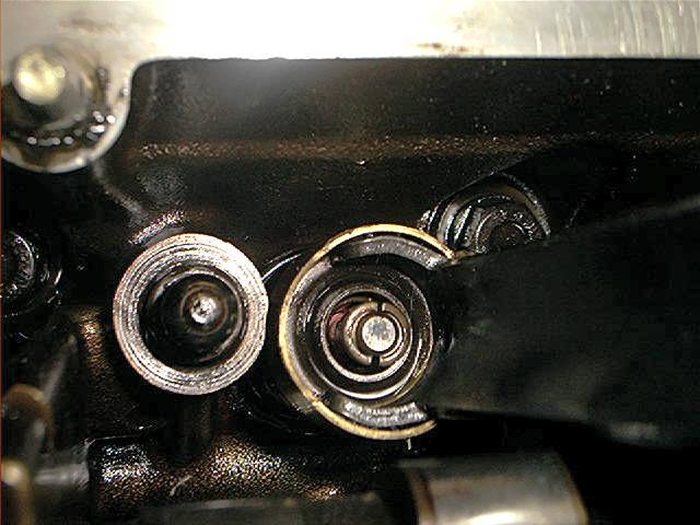
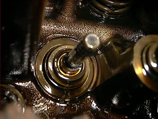
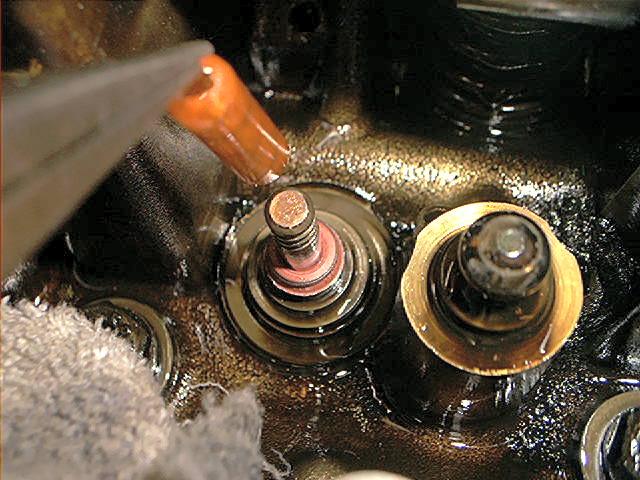
The exposed valve guide with the inner and outer lower spring retainers:
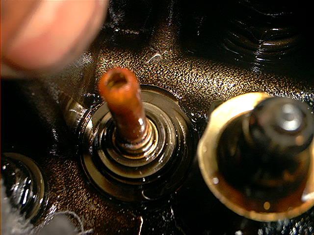
The new valve stem seals comes with a couple of plastic guides, to prevent damage to the new seal while installing it:
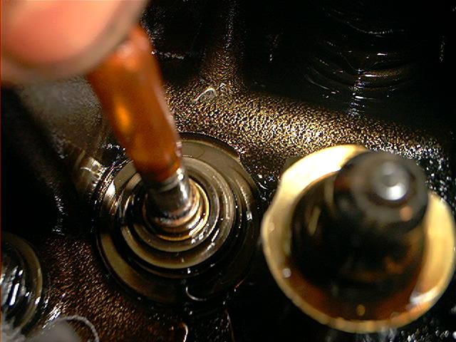
Install the new seal:
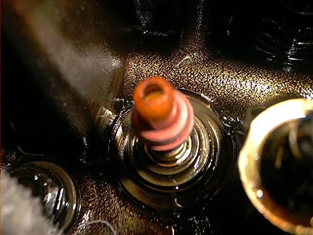
Push it down until you can’t push it further:
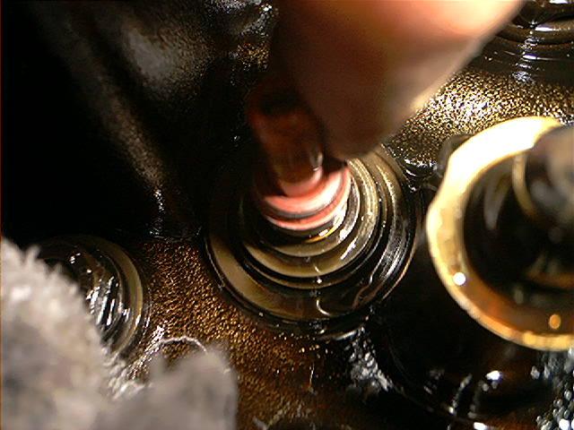
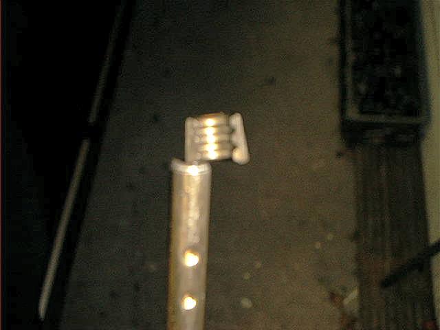
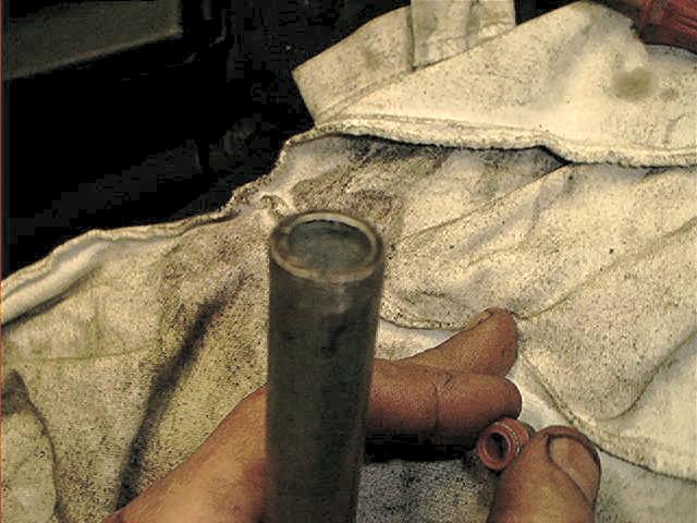
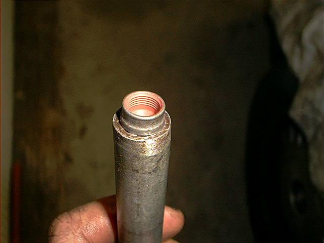
You need another special tool to install the seal completely. I used a small steel pipe for this:
Notice the inner side of the seal has some grooves that will hold seal in its place:
Use a small rubber hammer to press it onto the valve guide. Use some slight hammering and be very, very careful.
The knocking sound will tell you if it’s pressed all the way down (comes with experience):
Don’t forget to remove the plastic guide:
So . . . one down, 23 to go. Just keep on going . . . take your time . . . after cylinder #12, you can do this blindfolded.
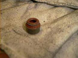
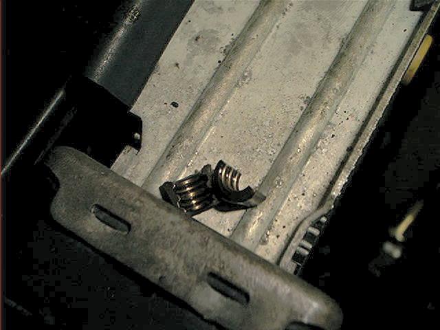
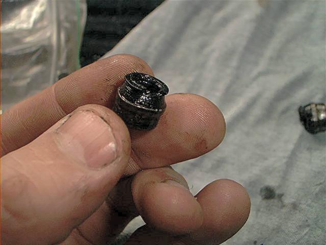
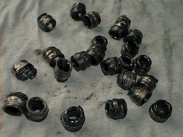
The completely worn old seals, stiff and brittle:
Keep the old seals so you are sure you’ve done them all (don’t count them…there are 24 seals, trust me on this):
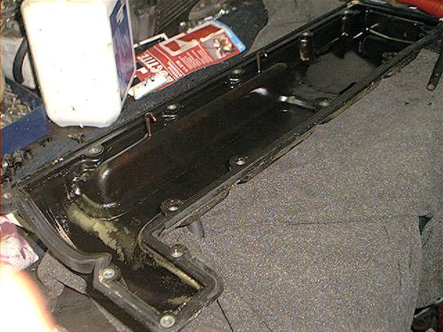
I also replaced the valve cover gaskets due to some oil leakage at the driver side. If it leaks badly, this could cause engine fires:
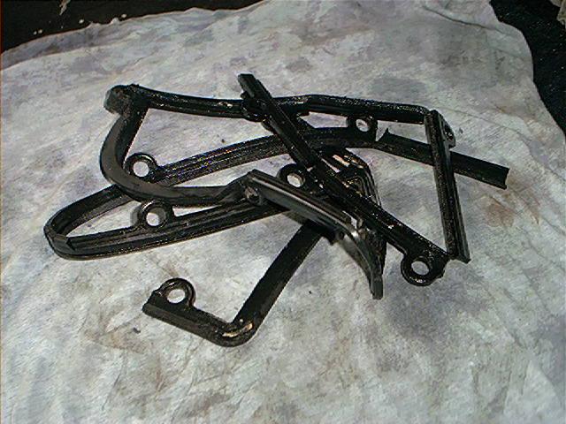
The old gasket broke into little pieces when removing it. No surprise it leaked. As most parts, cooked and brittle due to the extreme high engine temperatures under the hood:
Installing the new (original BMW) gasket. It was a completely different & better design:
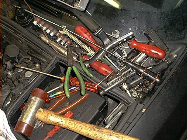
This picture doesn’t add much to the story, but gives a nice impression how much tools you need during the job (if you are as chaotic as I am).
At least 5 tools dropped down next to the fusebox/E-box and caused lots of frustrations:
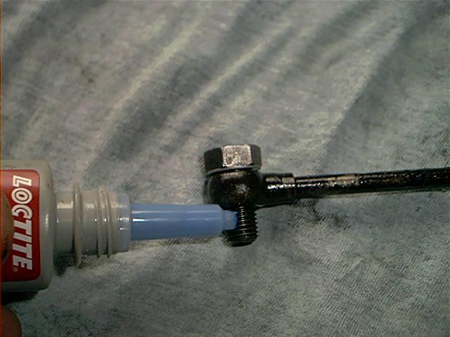
Reinstalling the oil spraying bar. Sealing the banjo bolts of the oil spraying bar (thoroughly decrease it before you apply sealant, clean also the bores):
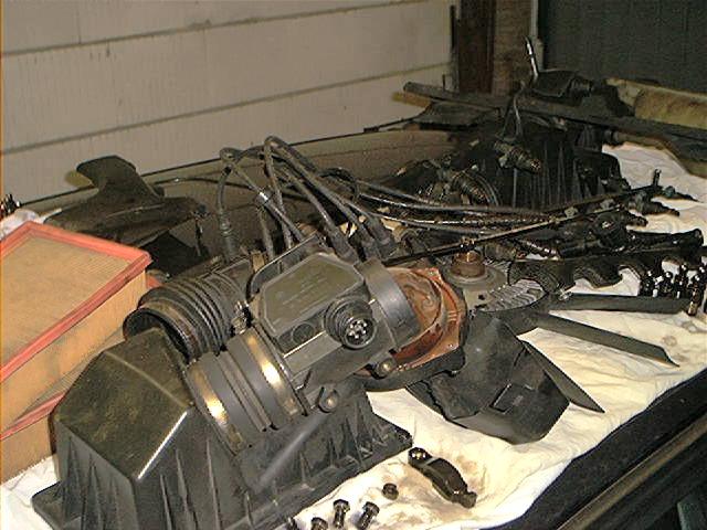
Roof covered with parts waiting for reinstall:
I also resealed the intake gaskets, check the section ‘intake manifold’ for the newly added pictures to this story.
Total amount of parts and costs (1 Euro equals about 1 US dollar) :
| BMW Part Number | Description | Price | QTY |
| 11349059172 | Valve seal repair kit | $53.13 | 2 |
| 11121725003 | Valve cover gasket left | $40.72 | 1 |
| 11121725002 | Valve cover gasket right | $40.72 | 1 |
Making a total of about 188.00 euro/US dollar. The valve cover gaskets are…..are…..HOW MUCH?!
Total amount of time: Gee, don’t underestimate this. It took me 3 full days, in total about 30 hours, to do this job. But this is including fabricating the special tools and fiddle around with the Midlock tool. I also resealed the intake gaskets and replaced the hydraulic lifters.
Skills needed/difficulty level: No easy task, definitely not. Skinned knuckles and pain in the back.
Something improved after a couple of weeks of driving: the blue smoke screen absolutely decreased, but didn’t disappeared entirely. The oil consumption dropped a tiny little bit, not as much as I hoped.
Well, it was worth the shot. On the contrary: the engine idles smooth like never before, no oil leakage from the valve cover gasket anymore and the camshafts are swimming in oil. So this weekend wasn’t spoiled, OK?