Article by: Sean – Additional comments and pictures by Cor Verlinde
Applies to: all e31, e32, and e38 models with the M70 V12 engine.
Someone we (Johan and I) know through our website contacted us that he had started an interesting project.
He was planning to build a Cobra replica. Not powered by the average cast-iron Mouse or Rat V8, nor or a slant six or obscure 4-banger.
He (Cor Verlinde) decided to use a REAL engine, that mighty alloy high tech short-stroke 5 liter beloved & trusty BMW V12 (we are not biased) ;-).
So he bought himself a tired ’90 750i and used it as a donor for his project.
The idea was to pull the engine, give it some cleaning and painting, replace common seals and shoe-horn it into the engine bay of the Cobra.
BUT: the former owner of the 750i was at a certain point where he could barely afford to pay the fuel. When he couldn’t spend even that money anymore, he decided to sell the car.
Now the v12 is a forgiving engine, but not when it comes to neglecting and lack of maintenance. Cor faced some unpleasant surprises when disassembling his engine…
This is the story about partially rebuilding a tired v12 with 270.000 km and getting a second life in a cobra.
The photo’s are taken by Cor, some additional comments (based on what I saw on the photo’s and Q&A’s with Cor) are made by Sean. Cor, thank you very much for this contribution.
Pulling the engine:
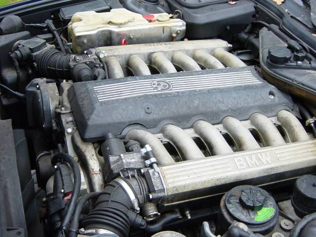
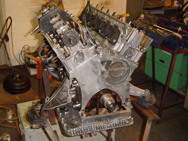
The engine of the old 750i. You can tell that the engine hadn’t been running for quite a while by the slightly corroded alloy parts.
One distributor cap looked like its been replaced, the coolant reservoir seemed somewhat contaminated. It’s the first model v12, with the oil filler cap at the right.
Someone messed around with the plugged vacuum hose connections of DK motors (the bolt with a hose and 2 hose clamps are not original):
Cor about the car: ‘the car had not been running for half a year. After that, it wouldn’t run on 12 cylinders anymore.
After replacing some leads and spark plugs it fired up and blew lots of dirt and water right out of the exhaust. After that, it was running smooth!
A 300km trip with the car showed no problems whatsoever and my intention was to remove the engine, clean it and bolt it into the Cobra. Oh boy, did I make a mistake.’
Dismantling the front of the car, to make removal easier. At last there is some easy access to the ABS pump:
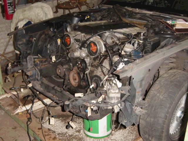
And from the right. The 2 loose aluminum pipes right in front of the engine are from the a/c condenser connection.
Notice the heavy shock-absorbers of the front bumper:
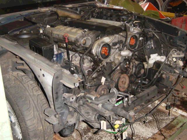
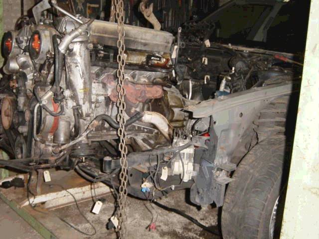
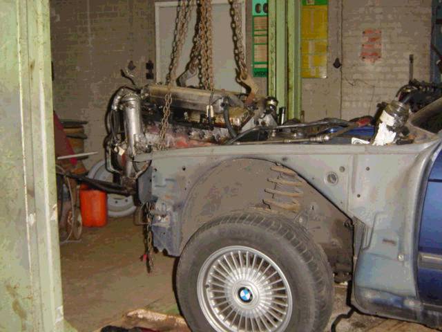
Actual pulling of the engine, together with the transmission. Now you can see how unreachable that alternator is.
The oil filter canister is still attached to the engine, I personally wouldn’t do that.
A part of the exhaust (probably just the down pipe) is still connected:
Notice the absolute lack of rust behind the left fender:
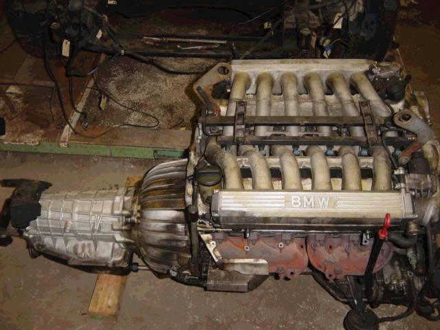
The engine and transmission. Wiring loom already removed. Notice the engine hoist brackets (not original):
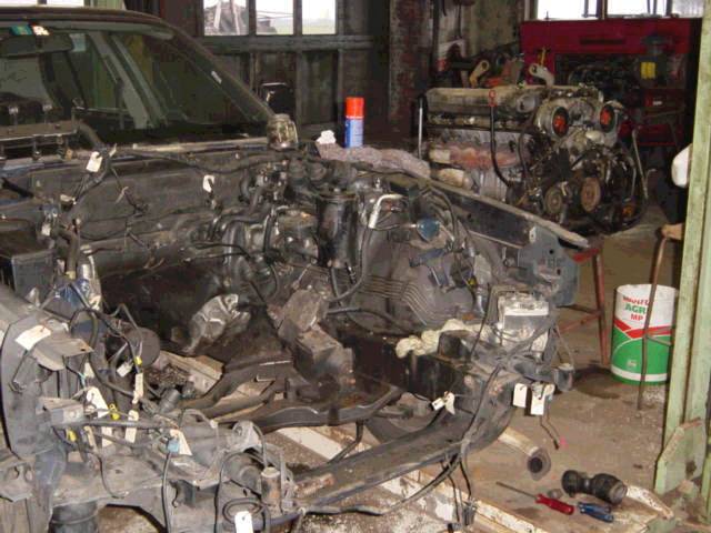
Empty engine bay:
The removed wiring harness/loom.
You wouldn’t say it, but this is the complete wiring harness of the engine shaped like its more or less attached in the engine room:
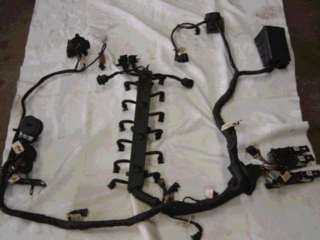
A removed (more or less) fuse/relay box:
![Dsc01219[1]](https://www.shiftbmw.com/wp-content/uploads/2013/04/Dsc012191.jpg)
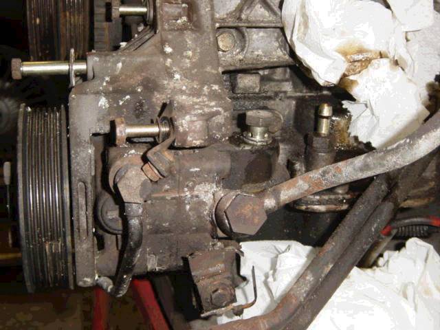
Unbolting the hydraulic pump from the engine. Notice the hose connection next to the right of the pump, that gave me some thinking.
This is actually the hose connection for the drain hose from the oil filter canister to the upper oil sump.
Usually impossible to reach:
Removed cover of the oil supply and return connections to the oil filter canister:
![Dsc01377[1]](https://www.shiftbmw.com/wp-content/uploads/2013/04/Dsc013771.jpg)
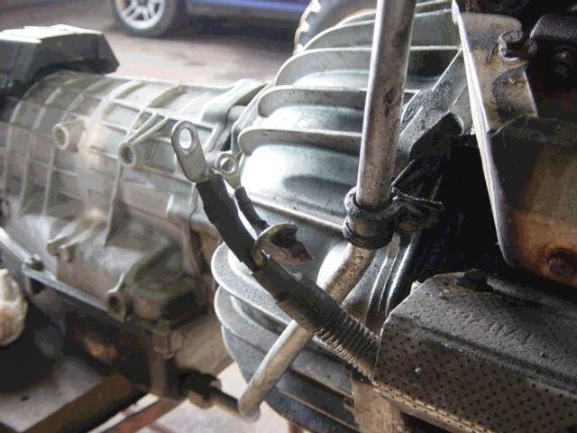
Disconnected leads to the starter. The starter is located behind the heat shield at the bottom-right.
Behind the leads the fill-tube for the tranny:
Removed air conditioning compressor. Lower and upper oil pan still attached:
![Dsc01378[1]](https://www.shiftbmw.com/wp-content/uploads/2013/04/Dsc013781.jpg)
Cor about this: ‘When I pulled the engine, I was shocked to see how full of oil and debris the outside of the engine was.
There was a good chance the engine suffered in the past from a small engine fire because of some small melted parts.
Probably because the thick battery terminal wire from the alternator shorted within his metal housing.’
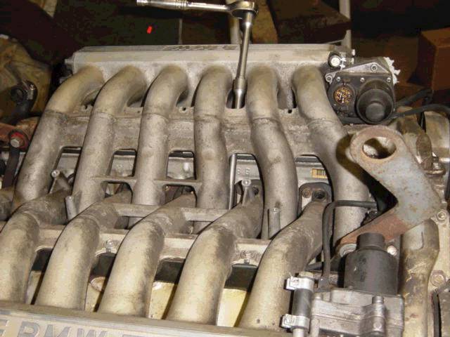
Unbolting the intake manifolds. Here you see you have excellent access if you remove the noise suppressors (located underneath each manifold) first.
At that point you don’t need to use swivels, just some extensions (1/4″):
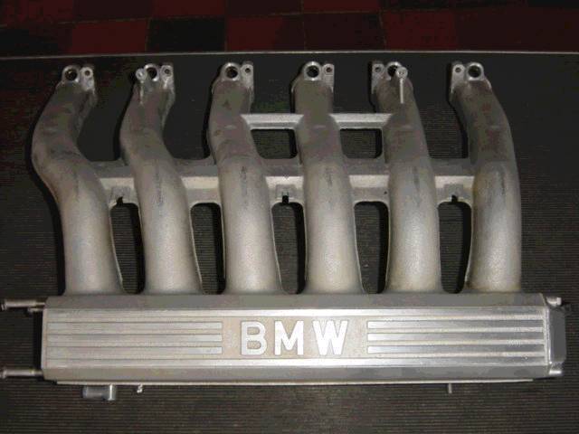
Removed and probably cleaned intake manifold in all his beauty.
Did you know that left and right are 1:1 identical (and thus interchangeable)?
Excellent castings:
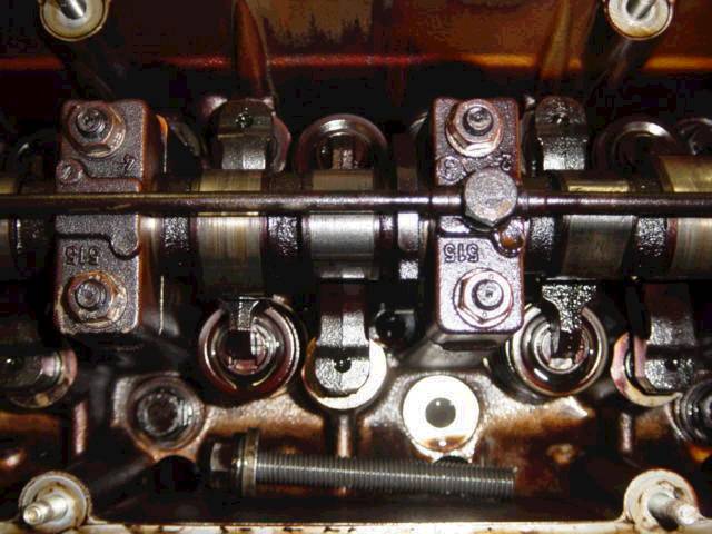
This is where the trouble began after removing the valve covers. A sheared off head bolt laying around at the bottom of the picture.
The empty hole just above it is the place where it originally was located.
Notice that these are torque-to-yield head bolts, recognizable to the windings from top to bottom:
Cor about this: ‘it never was my intention to pull the heads. I just removed the valve covers to clean the engine.
I was really worried and disappointed when I saw the contaminated inside of the engine, worn cams and the sheared head bolt laying around.
The broken bolt surprised me, because I never experienced symptoms of a blown head gasket (also engine temperature during the test run was normal).
After I saw this mess, I decided to tear the engine apart.’
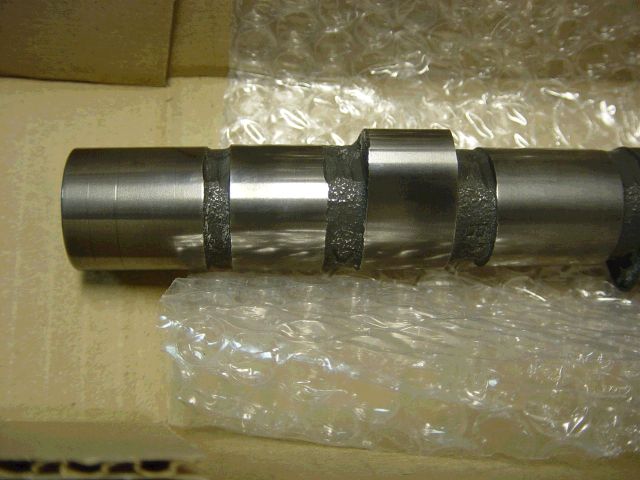
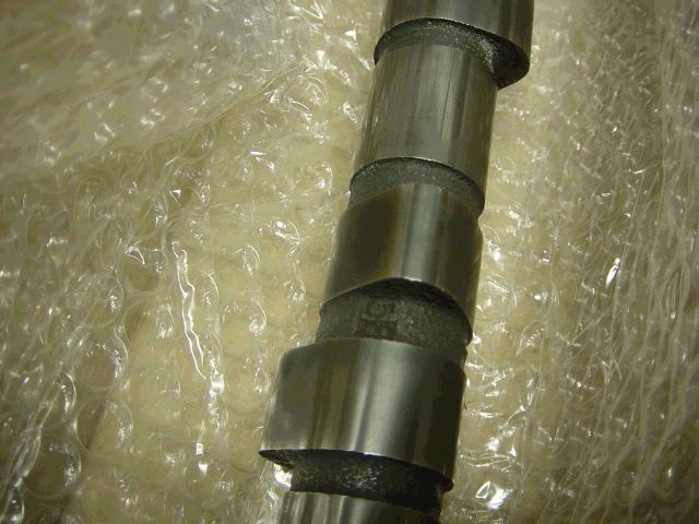
Also both cams where in bad shape, probably due to insufficient oil supply (loose banjo bolts of the oil spraying bar) or inferior oil quality:
![Dsc01386[1]](https://www.shiftbmw.com/wp-content/uploads/2013/04/Dsc013861.jpg)
![Dsc01391[1]](https://www.shiftbmw.com/wp-content/uploads/2013/04/Dsc013911.jpg)
![Dsc01393[1]](https://www.shiftbmw.com/wp-content/uploads/2013/04/Dsc013931.jpg)
Upper timing covers removed, revealing the camshaft sprockets and timing chain:
![Dsc01374[1]](https://www.shiftbmw.com/wp-content/uploads/2013/04/Dsc013741.jpg)
Definitely sludge/crud buildup and deposits in this engine. Probably the previous owner used el-cheapo oil or didn’t bother to change the oil at all.
I just hate it when people f*ck up their engine this way. This is the reason why you should use a good brand oil and change the oil frequently:
![Dsc01375[1]](https://www.shiftbmw.com/wp-content/uploads/2013/04/Dsc013751.jpg)
The removed water pump. Luckily the PO used coolant and not plain water, considering the overall condition of the engine.
The unbolting of the lower timing case cover has started:
![Dsc01376[1]](https://www.shiftbmw.com/wp-content/uploads/2013/04/Dsc013761.jpg)
Removal of the exhaust manifolds with an air wrench, behind the air wrench is the oil filler tube.
Notice that the upper timing case cover leaked severely, a common problem with early V12’s (there is actually a BMW service bulletin about this problem):
![Dsc01382[1]](https://www.shiftbmw.com/wp-content/uploads/2013/04/Dsc013821.jpg)
Removed exhaust manifolds. At the right, the big bolt sticking out next to the lower timing chain cover, is the timing chain tensioner (also infamous for oil leakage).
Notice that 1 stud stayed in the cylinder head:
![Dsc01397[1]](https://www.shiftbmw.com/wp-content/uploads/2013/04/Dsc013971.jpg)
The other side with removed exhaust manifolds. If you look closely, you’ll see the actual exhaust valves.
Again, 1 stud stayed in the cylinder head (by accident).
The central bolt below exhaust port number #10 (third from right) is the coolant drain plug of the engine itself:
![Dsc01383[1]](https://www.shiftbmw.com/wp-content/uploads/2013/04/Dsc013831.jpg)
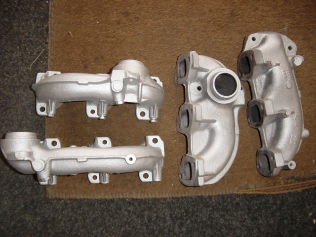
Old versus bead blasted exhaust manifolds (more on bead blasting later):
![Dsc01384[1]](https://www.shiftbmw.com/wp-content/uploads/2013/04/Dsc013841.jpg)
![Dsc01385[1]](https://www.shiftbmw.com/wp-content/uploads/2013/04/Dsc013851.jpg)
Starter removed, but torque convertor is still attached to the flywheel:
![Dsc01399[1]](https://www.shiftbmw.com/wp-content/uploads/2013/04/Dsc013991.jpg)
You don’t see the back of the engine very often. The intake manifold gaskets are still attached.
Between them is the plumbing of the coolant system.
Now you have a good look at the coolant cross-over pipe (aka coolant collector) between the cylinder heads.
Normally very hard to reach. Also you can see the 3 coolant sensors (from left to right:
1 for both DME’s, 1 for EML and 1 for your temp gauge)
![Dsc01405[1]](https://www.shiftbmw.com/wp-content/uploads/2013/04/Dsc014051.jpg)
All bolts of the lower timing chain cover removed, crankshaft pulley and damper removed.
You now see that it isn’t necessary to remove the big crankshaft bolt to remove the crank pulley.
And that is a good thing. The upper crankshaft position sensor is removed, the lower one still attached:
![Dsc01373[1]](https://www.shiftbmw.com/wp-content/uploads/2013/04/Dsc013731.jpg)
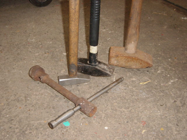
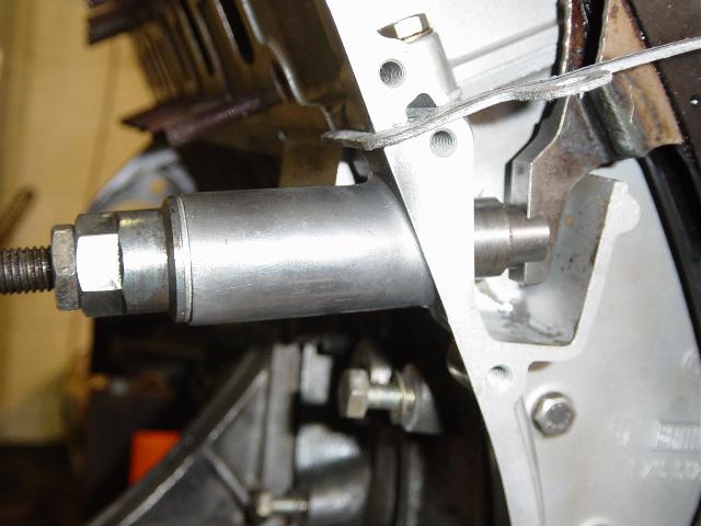
But this was a tough one, the big crankshaft bolt. Its bolted on with a staggering 440 Nm and you can’t reuse this bolt, it’s torque-to-yield and a beast to remove.
Cor about this: “Even an air impact wrench didn’t do the job. Only the largest hammer I could find in combination with an incredible whack did it.
Normally we use these kind of brute force for agriculture machines, not lightweight alloy v12’s”:
![Dsc01381[1]](https://www.shiftbmw.com/wp-content/uploads/2013/04/Dsc013811.jpg)
Draining the engine oil: black as the night:
![Dsc01398[1]](https://www.shiftbmw.com/wp-content/uploads/2013/04/Dsc013981.jpg)
For removing the upper oil pan you need to remove transmission, torque convertor and flywheel:
![Dsc01400[1]](https://www.shiftbmw.com/wp-content/uploads/2013/04/Dsc014001.jpg)
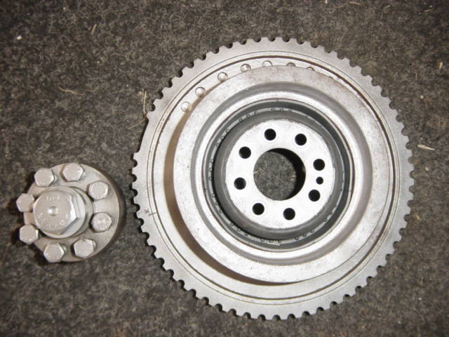
The torque converter:
![Dsc01543[1]](https://www.shiftbmw.com/wp-content/uploads/2013/04/Dsc015431.jpg)
. . . and starting gear.
![Dsc01544[1]](https://www.shiftbmw.com/wp-content/uploads/2013/04/Dsc015441.jpg)
A truly magnificent photo. Upper and lower timing case covers removed.
If you look closely you can see the gaskets between the removed upper and lowers case covers hanging loose and upper oil pan removed.
You can see clearly the primary timing chain and the secondary oil pump chain:
![Dsc01402[1]](https://www.shiftbmw.com/wp-content/uploads/2013/04/Dsc014021.jpg)
Upper oil pan, quite dirty:
![Dsc01403[1]](https://www.shiftbmw.com/wp-content/uploads/2013/04/Dsc014031.jpg)
A beautiful close-up of the oil pump, timing chain removed. This chain can be simply adjusted (more on this later):
![Dsc01407[1]](https://www.shiftbmw.com/wp-content/uploads/2013/04/Dsc014071.jpg)
Cor about the oil pump: ‘I took the pump apart and it was full of debris. That was not good. Not good at all.’
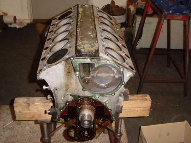
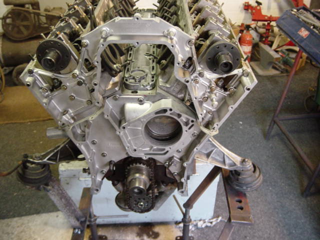
Beneath is a very rare picture that you won’t see often. This is the front of the engine, with timing chain and sprockets removed.
Also the back cover of the upper timing case cover is removed. This is very rare, usually people don’t remove this.
So the upper timing case cover exist out of 2 parts, the front cover and the back cover connected by a myriad of 10mm bolts.
I was surprised to look at the coolant connections at the front of the engine.
It seems that the coolant cross-over pipe could also be at the front of the engine (same connections, same bolt pattern).
This is because the cylinder heads have the same castings.
So left and right are identical. Furthermore look at that unusual high cam towers:
![Dsc01408[1]](https://www.shiftbmw.com/wp-content/uploads/2013/04/Dsc014081.jpg)
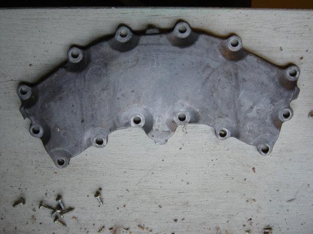
The backside of the removed back timing case cover, you can see clearly the covering of the coolant channels:
![Dsc01409[1]](https://www.shiftbmw.com/wp-content/uploads/2013/04/Dsc014091.jpg)
Left cylinder head removed to remove the broken piece of the head bolt:
![Dsc01411[1]](https://www.shiftbmw.com/wp-content/uploads/2013/04/Dsc014111.jpg)
The left cylinder head with old gasket:
![Dsc01415[1]](https://www.shiftbmw.com/wp-content/uploads/2013/04/Dsc014151.jpg)
An overview:
![Dsc01429[1]](https://www.shiftbmw.com/wp-content/uploads/2013/04/Dsc014291.jpg)
This is a remarkable photo. The back part of the lower timing case cover can be removed:
![Dsc01430[1]](https://www.shiftbmw.com/wp-content/uploads/2013/04/Dsc014301.jpg)
Examination of the cylinder walls. Normally you have no signs of wear, tear and grooves.
These silicon hardened cylinder walls have an extremely tough surface. At the bottom the remains of the broken head bolt:
![Dsc01412[1]](https://www.shiftbmw.com/wp-content/uploads/2013/04/Dsc014121.jpg)
![Dsc01413[1]](https://www.shiftbmw.com/wp-content/uploads/2013/04/Dsc014131.jpg)
![Dsc01414[1]](https://www.shiftbmw.com/wp-content/uploads/2013/04/Dsc014141.jpg)
Cor about the 3 pictures above:
“The cylinder walls didn’t have edges, scratches, sign of wear and tear and looked like brand new. I didn’t do a thing about them”.
Close-up of the remains of the broken head bolt:
![Dsc01420[1]](https://www.shiftbmw.com/wp-content/uploads/2013/04/Dsc014201.jpg)
You need a special tool for this, Cor used left-handed screw extractors:
![Dsc01421[1]](https://www.shiftbmw.com/wp-content/uploads/2013/04/Dsc014211.jpg)
Covering the coolant and oil passages (I personally would cover also the cylinders) to prevent debris falling in while drilling.
A hole is drilled in the center of the stud:
![Dsc01422[1]](https://www.shiftbmw.com/wp-content/uploads/2013/04/Dsc014221.jpg)
Removing the broken head bolt:
![Dsc01423[1]](https://www.shiftbmw.com/wp-content/uploads/2013/04/Dsc014231.jpg)
![Dsc01425[1]](https://www.shiftbmw.com/wp-content/uploads/2013/04/Dsc014251.jpg)
Operation succeeded:
![Dsc01426[1]](https://www.shiftbmw.com/wp-content/uploads/2013/04/Dsc014261.jpg)
1 cleaned sprocket versus the other. Cor didn’t replace them, the local BMW dealer told him the chain and sprockets looked fine:
![Dsc01431[1]](https://www.shiftbmw.com/wp-content/uploads/2013/04/Dsc014311.jpg)
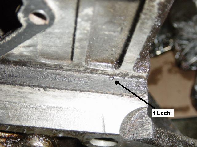
The other cylinder head will be removed. First he identified the thickness of the original head gasket.
There are 2 types of thickness, identified by a small hole in the head gasket. The 2 hole version is thicker.
This is visible without removing the head (1 loch means 1 hole).
Cor about this: “This is important. The thickness of the head gasket has influence on the size of the timing case cover gaskets”.
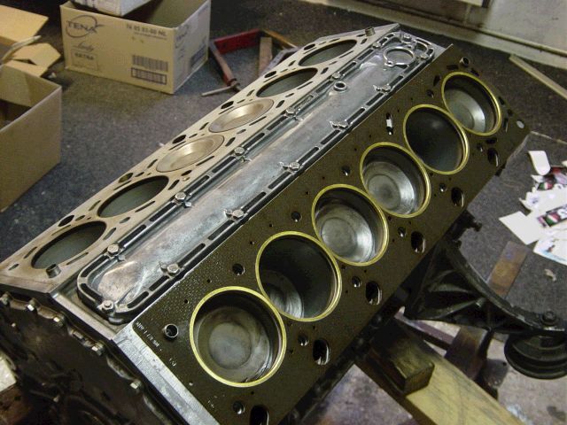
Removed head gasket with the small hole. This is important when replacing the head gasket and order a new one:
![Dsc01467[1]](https://www.shiftbmw.com/wp-content/uploads/2013/04/Dsc014671.jpg)
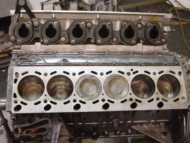
Disassembling more parts:
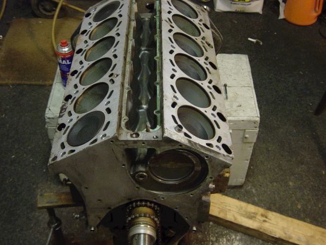
Both heads and central gallery cover are removed.
The coolant is pumped from the water pump directly through this central ‘channel’ to the back of the engine:
![Dsc01540[1]](https://www.shiftbmw.com/wp-content/uploads/2013/04/Dsc015401.jpg)
So lots of coolant will be flowing through this:
![Dsc01542[1]](https://www.shiftbmw.com/wp-content/uploads/2013/04/Dsc015421.jpg)
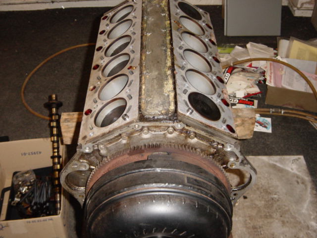
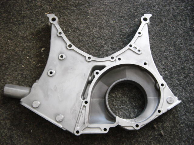
At the rear of the engine, removal of the rear main seal and rear coolant channel cover.
Now you can see that the crankcase is symmetrical and the starter could also be mounted at the other side of the engine.
This is actually the case where people use to drive at the wrong side of the road.
Look at the block casting, you can actually see the outer cylinder walls castings and the hole of the central coolant channel:
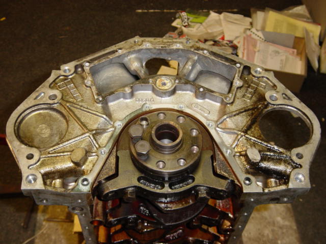
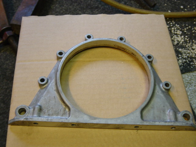
Removed case of the rear main seal:
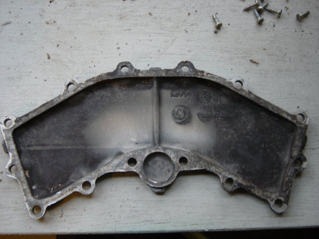
Removed cover of rear coolant channel:
The engine from underneath. This is a highly interesting picture.
You see that 2 pistons are sharing the same crank journal and that its actually a four bolt main block (you look at the main bearing caps).
Obvious the reason why the bottom-end is so very strong. It almost never needs a rebuild:
![Dsc01539[1]](https://www.shiftbmw.com/wp-content/uploads/2013/04/Dsc015391.jpg)
Cor removed just one lower rod bearing cap, to examine the bearing surface and the crank journal surface. They looked immaculate:
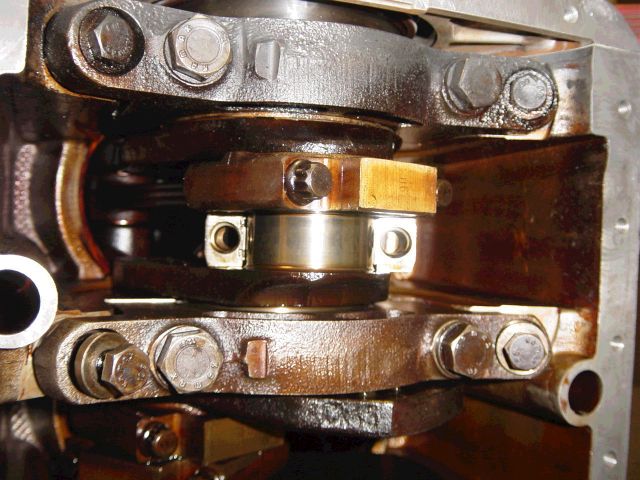
A close up of the bearing surface. Folks, this is a bearing surface after 270.000 km (170k miles) in a heavily neglected engine.
One more proof the bottom end of the v12 is an extremely tough design. Don’t you just love those BMW engineers?:

Disassembly of the oil pump. If you look closely, you can see the pump is actually 2 pumps integrated (Eaton tandem type).
One scavenger pump for oil pick-up, and one for the actual oil pressure supply:
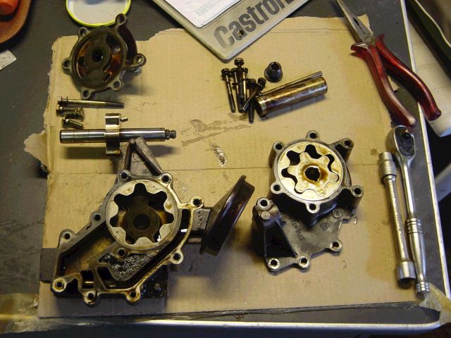
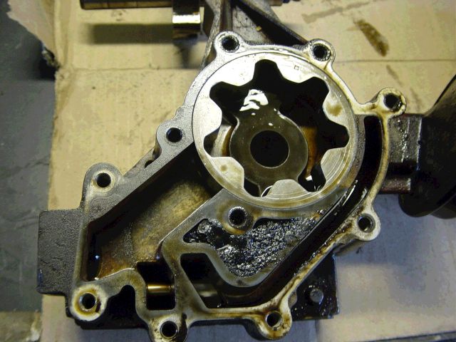
A close-up of the oil pump. You’ll see some crud build-up:
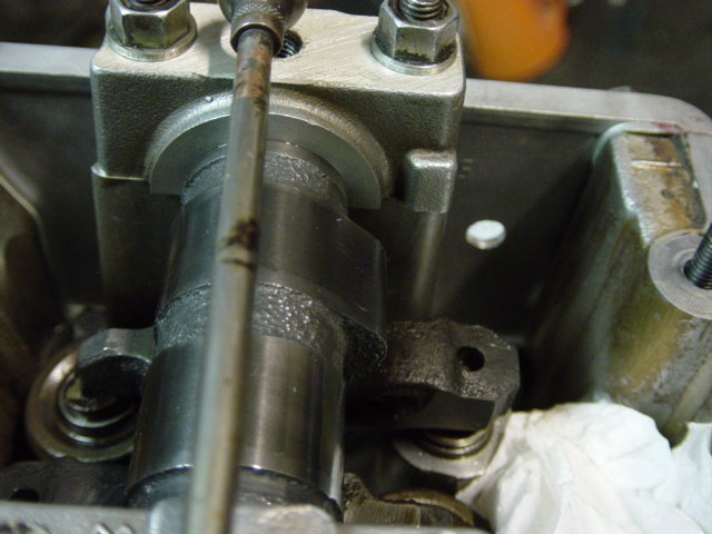
Back to the heads. Removal of the valves. He used a special tool for this:
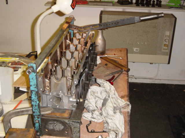
He removed the camshafts for a rebuild (he didn’t replace them, more on this later).
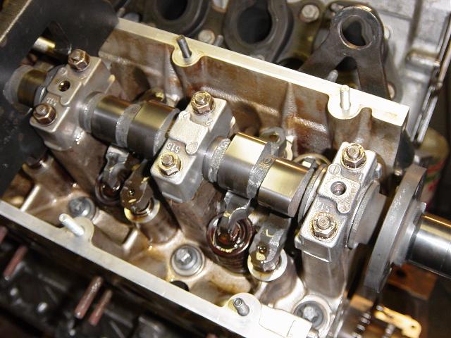
You can see that the camshafts don’t have separate bearings, but running directly in the heads:
![Cilinderkop[1]](https://www.shiftbmw.com/wp-content/uploads/2013/04/Cilinderkop1.jpg)
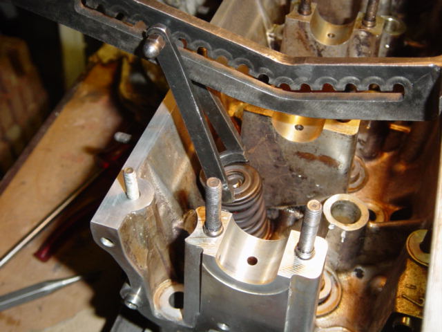
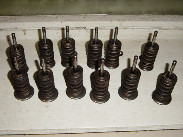
Valves removed (from 1 head). Cor marked each valve so he was sure the valves where reinstalled in the same position:
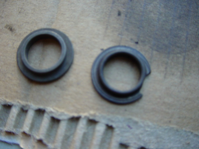
One lower outer spring retainer got damaged while disassembling.
It must be replaced or else the forged steel could severely damage the soft alloy of the cylinder head:
Close-up of an inlet valve. It looked like new after 270.000 km, so he didn’t replace them:
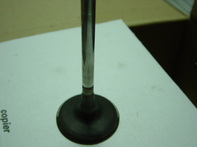
Cor just slightly reground the valve stem surfaces when reinstalling the valves because some carbon build-up.
The blue box contains the grinding paste:
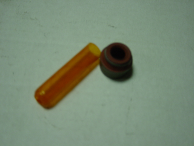
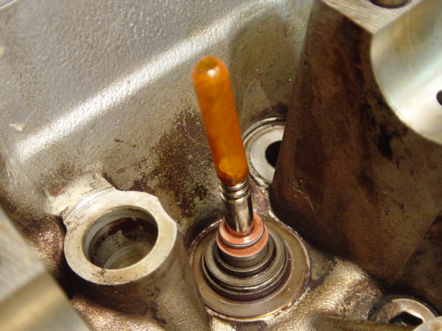
He did replace the valve stem seals. This is one seal, the little orange ‘tube’ is to prevent damaging the new valve stem seal when installing:
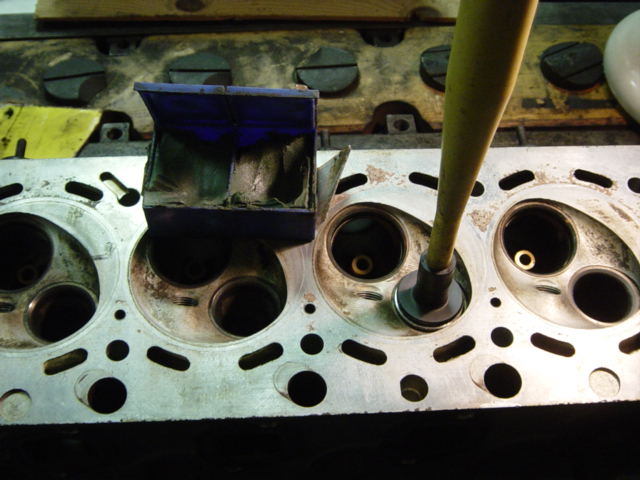
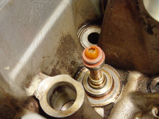
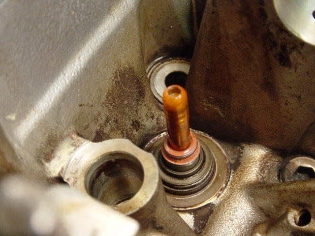
The valve is installed, so he covered the valve guide with the orange ‘thingy’ and installed the valve stem seal:
![Klepsteelafdicht[1]](https://www.shiftbmw.com/wp-content/uploads/2013/04/Klepsteelafdicht1.jpg)
If you look closely, he made an error in the first 2 pictures of the valve stem replacement.
Translation of text beneath: ‘the inner and outer valve spring retainer must be first installed prior to the valve stem seal installation’:
![klepsteelafdichting[1]](https://www.shiftbmw.com/wp-content/uploads/2013/04/klepsteelafdichting1.jpg)
After rebuilding the heads, Cor decided to clean the alloy and metal parts. For cleaning of the parts, Cor used the glass bead blasting procedure.
An explanation from somebody else about this: “The most common abrasive used is glass beads. They look like fine white sand.
They are good for rust but do not take off paint easily and hard paint sometimes not at all.
The beads do not erode the metal as sand does so does not get off the real deep rust.
It does leave a lot smoother finish though and is good for brass, bronze and aluminum.”
Therefore glass bead blasting is excellent for alloy parts.
Cor: “For the metal parts like the exhaust manifolds, valve covers and the lower oil pan I used metal grit.
I tried it also on some alloy parts (not from the v12) but that gave a devastating result. Therefore I used glass beads.”
The metal parts finally got a paint finishing to protect the parts against rust.
The alloy parts weren’t treated after the blasting (or sometimes just a slight polishing).
![Dsc01452[1]](https://www.shiftbmw.com/wp-content/uploads/2013/04/Dsc014521.jpg)
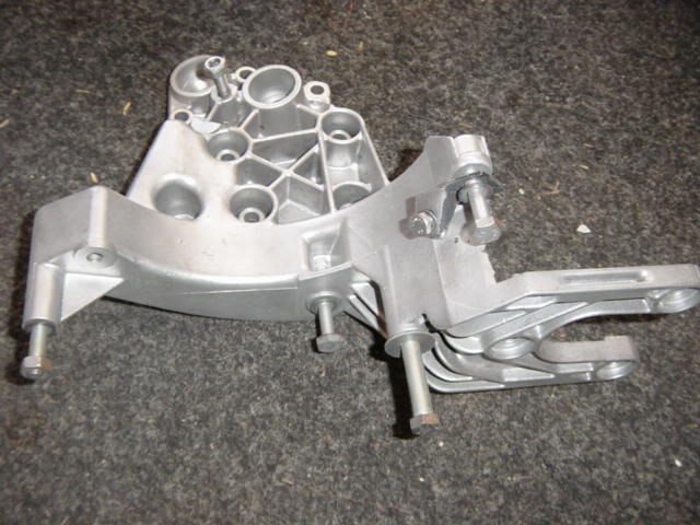
Here are the results of some glass bead blasting parts. This is the bracket for the hydraulic pump:
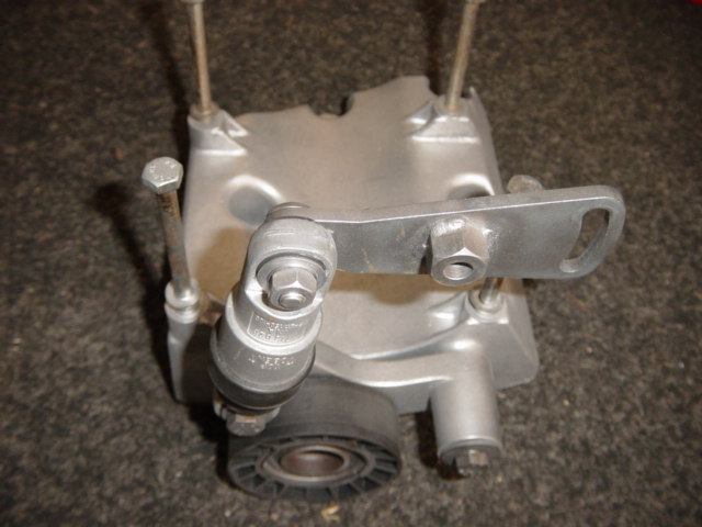
Air conditioner / water pump belt tensioner assembly:
Crankshaft pulley, hub and damper:
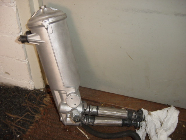
Oil filter canister:
Distributor housing:
Distributor housing after polishing:
The home-made polishing tool:

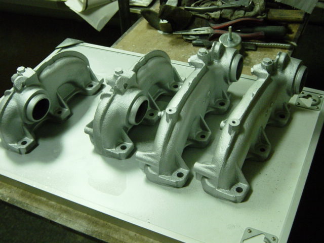
Exhaust manifolds after bead blasting and spraying:
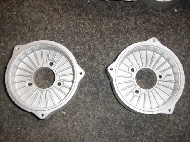
Coolant collector and cylinder head back and front covers:
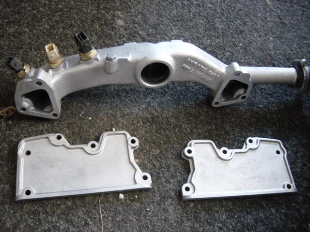
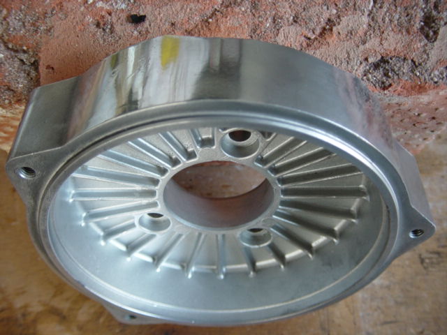
Backside of the lower timing case cover, backside. Also interesting picture. At the left (sticking out) the part where the timing chain tensioner belongs.
The water pump is mounted at the other side of this cover, the water pump impeller is protruding through the large hole.
The ‘snail house’ (couldn’t find the right word for it) is responsible for pumping the coolant through the cylinder gallery.
Look at the lower picture of the front of the engine how this cover is mounted to it:
For better understanding: this is where the cover above is mounted to.
You see the pump pumps coolant directly through the gallery to the back of the engine, distributed through the short block and after that squeezed through the coolant channels of the head gasket to the cylinder heads.
According to this construction, the front cylinders #1 and #7 will run hotter that others but that is not a big issue because this is the front of the engine (receiving lots of air flow).
Probably BMW engineered the coolant system this way so cylinders #6 and #12 near the firewall (normally the hottest, also at the straight sixes) won’t experience as much heat as cylinders near a firewall normally do.
So we can call this another excellent design:
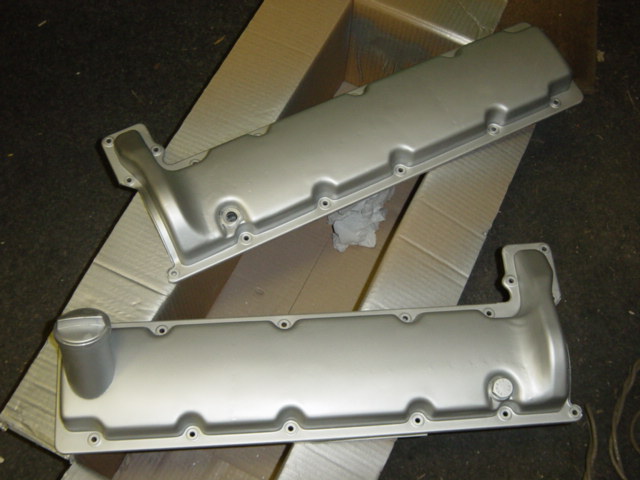
Valve covers cleaned and sprayed. The oil filler cap will be replaced:
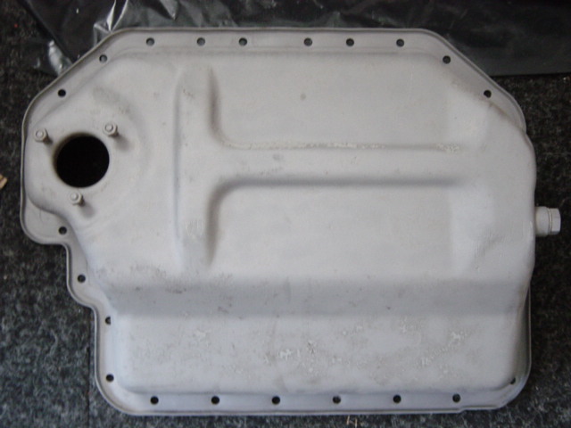
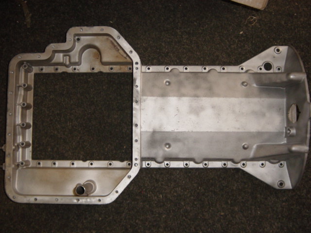
Lower oil pan. The big hole at the left is for the oil level sensor. Also, I think BMW got some discount on large quantities of 10mm bolts:
Upper oil pan:
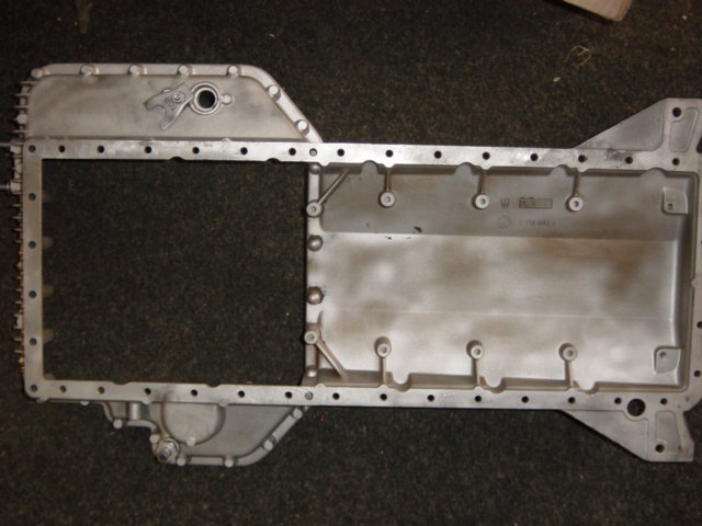
Notice the hole at the right. This hole is for unbolting the torque convertor from the flywheel:
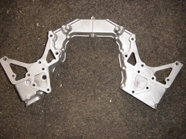
Back part of upper timing case cover, a complex alloy casting:
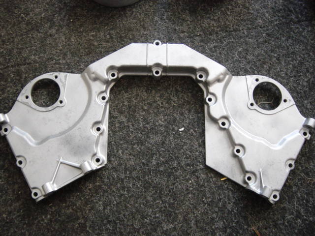
Front part of upper timing case cover:
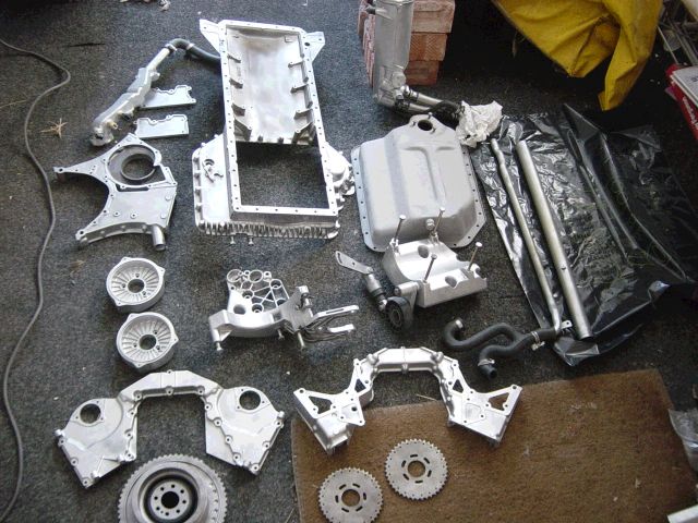
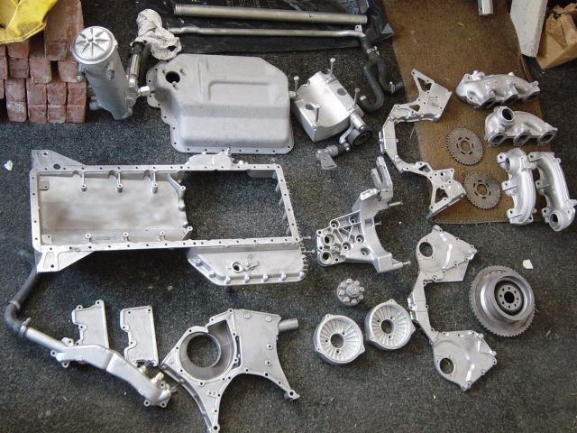
An overview of several cleaned parts:
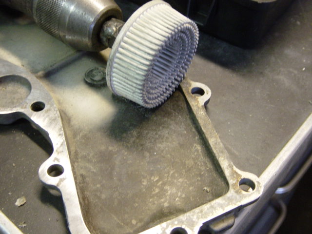
For some parts Cor used a special tool to remove the old gaskets. This because you can’t use a normal gasket scraper, it would damage the soft alloy surface:
After disassembling all parts and cleaning and spraying them, the hard part of reassembling the engine comes.
New gaskets and seals where purchased from the BMW dealer:
![Dsc01454[1]](https://www.shiftbmw.com/wp-content/uploads/2013/04/Dsc014541.jpg)
New gaskets and seals where purchased from the BMW dealer:

Because the old water pump had some play, a new pump was ordered:
![Dsc01457[1]](https://www.shiftbmw.com/wp-content/uploads/2013/04/Dsc014571.jpg)
And of course, new sets of head bolts:
![Dsc01458[1]](https://www.shiftbmw.com/wp-content/uploads/2013/04/Dsc014581.jpg)
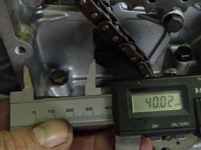
At first Cor decided to reinstall the oil pump. The chain of the oil pump must be adjusted, so at first he measured the slack:
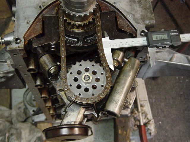
The actual chain slack must be 10mm +/- 2mm and can be adjusted by turning a hex bolt.
Cor about this: ‘this is an interesting design’
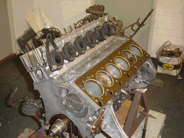
Reassembly begins. The large coolant cover at the back of the engine already installed, so as the cover of the central coolant channel.
First head gasket in place. Pay attention to the coolant channels in the head gasket: the cylinder at the front (rightmost) has larger coolant channel holes as the cylinders next to it.
This is probably because this cylinder is the last cylinder to receive coolant, which is pumped from back to front, so it gets a higher flow of coolant.
Another detail of this fine piece of machinery:
First cylinder head in place. The intake gaskets where reused (more on that later):
Second head gasket in place:
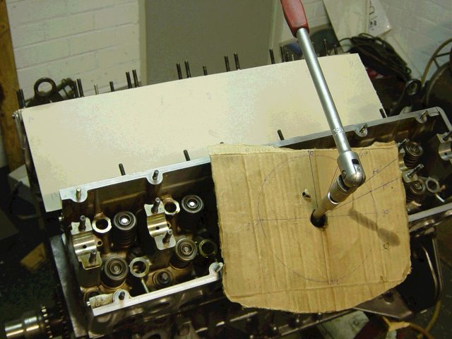
The tightening of the head bolts goes in 3 stages, where the last 2 stages are app. turning the head bolts +60 degrees.
You need some kind of pointer for this, but Core made his own home made pointer:
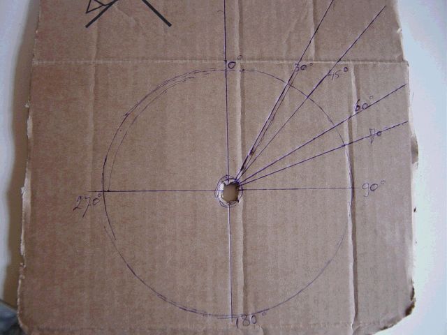
Which worked quite well:
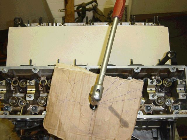
The cardboard at the back used Cor to make notes so he could identify which bolts where already tightened 60 degrees and which not.
You just don’t want to make a mistake when using yield-to-torque bolts:
After the head installation, both cams can be installed. As you may remember from earlier pictures, both cams where (slightly) worn.
New camshaft where just too expensive so Cor decided to regrind the cams.
After regrinding, the lobes were re-hardened:
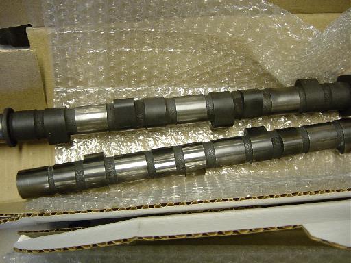
The black ‘coating’ on the lobes came from re-hardening the surfaces and was extremely tough to remove, according to Cor:
In my opinion, regrinding the camshafts is nothing more than removing a slight surface of the camshafts.
So its unlike welding the cam lobes, where you build up the lost material (and machine afterwards).
I should say this grinding affects the absolute valve lift (the relative valve lift *the distance the valve travels* stays the same.
The grinding process is also reducing the diameter of the base circle) because some material is removed from the top of the lobe.
Also the rocker position is slightly changed and hydraulic lifter corrects the different height to the cam, but according to Cor this difference is at a minimum.
My knowledge about rebuilding cams is not extremely good, so maybe a visitor from this site could elaborate more about this procedure.
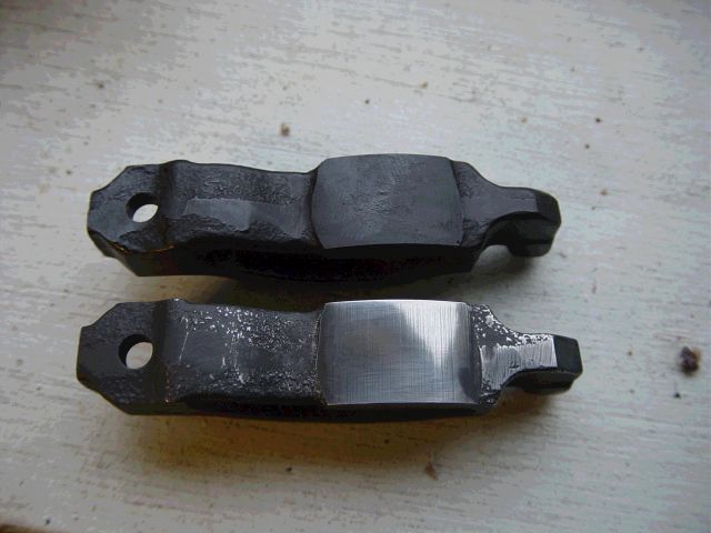
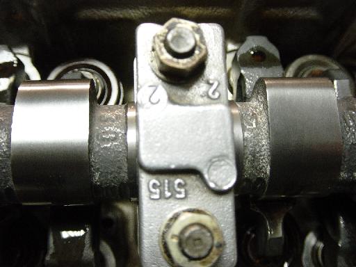
Also the rockers where replaced by new ones. That is not a bad decision, because the old rockers where ‘worn-in’ to the old camshaft surface.
The new rockers got an additional re-hardening treatment. Again the black deposits where very hard to remove:
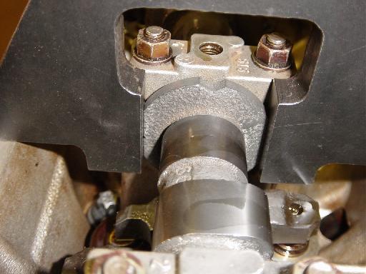
Fitting the cams to the engine. This is a sensitive job and the bolts must be equally tightened to prevent damaging the camshaft while tightening it.
Cor was warned for this after the re-hardening process of the camshaft:
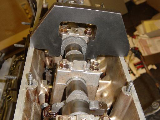
An overview. You’ll see the camshaft locking tool already installed, and the lower oil pan.
This was necessary to put the engine in TDC (locking the flywheel with a dowel).
Cor: “I didn’t know how much clearance there was between valves and pistons so I wanted to take no risk. I putted the engine in TDC and installed the camshaft locking tool.
After that, I tightened carefully the camshaft ensuring the valves (which are depressed while tightening the camshaft) don’t hit some piston.”
After the camshaft installation, the oil spraying bars could be installed. Ensure the holes are clean:
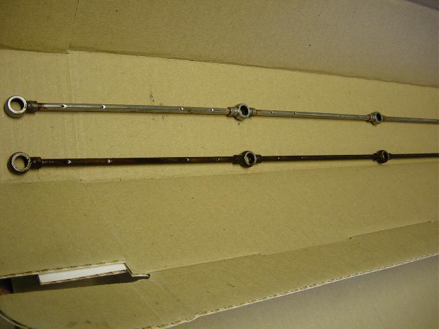
Almost everybody knows about the notorious problem of loose banjo bolts regarding these oil spraying bars.
Cor invented a clever system to examine the oil pressure at these bars (which is also the end of the internal oil routing of the engine).
He decided to make an extension to the oil bar and attach to the connection a separate oil pressure sender (that is one for each bank) at the back of each cylinder head.
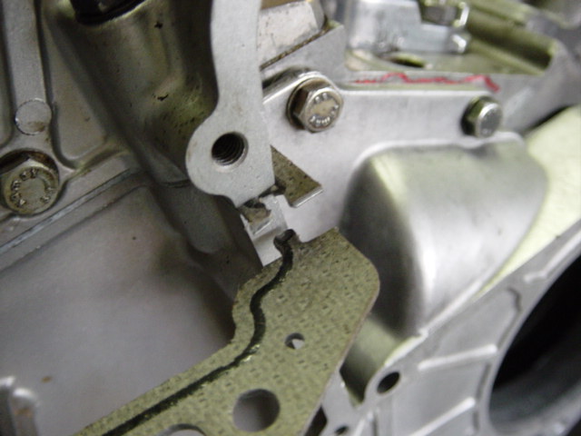
First he ground away the slight ‘hump’ on the cam bearing cap (picture underneath is without banjo bolt hole, but you get the point) to get enough clearance underneath the valve cover:
After grinding the cam bearing cap, just barely visible at the top of the picture:
Cor bought a larger banjo bolt and ground the head:
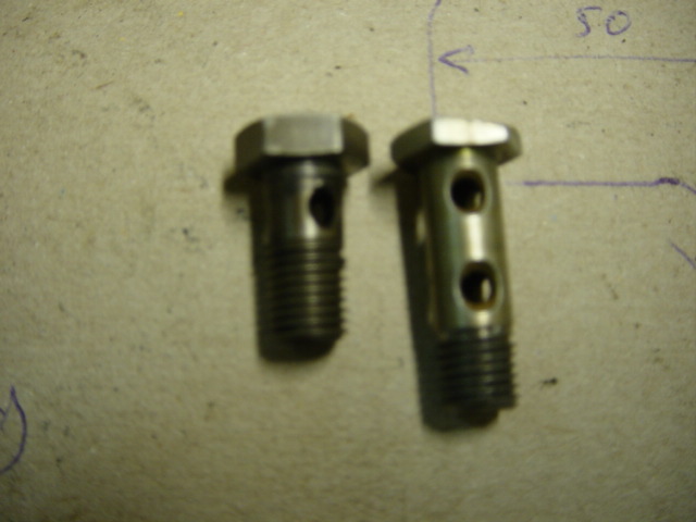
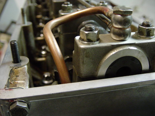
He made a special oil pressure line with 2 banjo connections:

And drilled a hole in the back of the cylinder head cover:
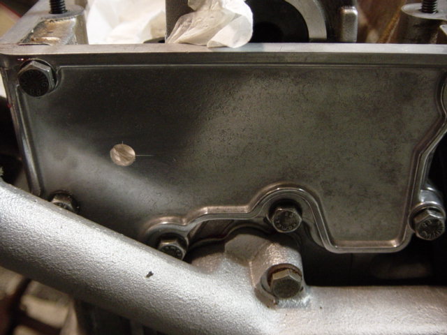
And bolted everything together:
After this, the timing case covers could be installed.
The lower back timing case cover is already installed, ready to install the water pump, and the upper back timing case cover is installed.
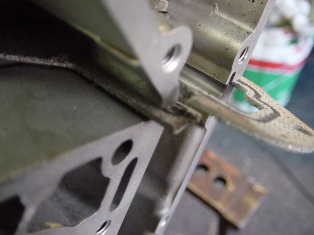
Notice the gaskets to seal the front upper and lower case covers:
The gaskets are actually fitting like a jigsaw piece into each other.
Now why is this? Because now you can R&R the timing chain without pulling the chain apart (or the gasket):
These are the gaskets between the front upper and lower timing case covers and back upper and lower covers:
Installing the timing chain tensioner:
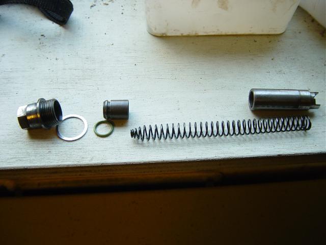
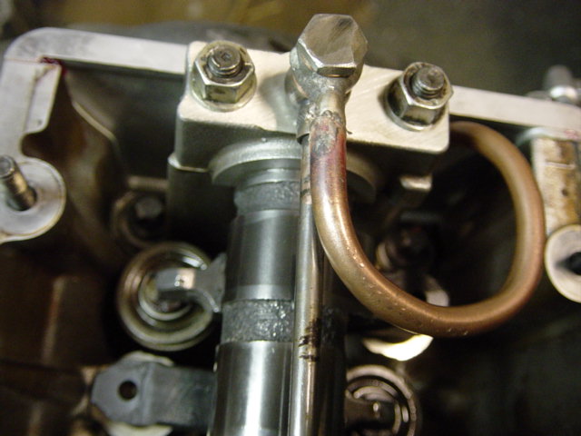
To adjust the timing, you must first lock the crankshaft at TDC. After that you lock the camshafts using a special tool (oil spraying bar removed for better understanding):
Tighten the cam sprockets just finger tight (notice the slotted holes):
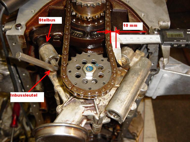
Measuring and adjusting the timing chain slack by turning the timing chain tensioner:
After this, tighten the cam sprocket bolts.
First the left, than the right. Cor: ‘it looks like an easy job but it surely wasn’t.
After turning the engine by hand for several times, the timing adjustment was again incorrect so I had do this over and over again until the timing was right.’
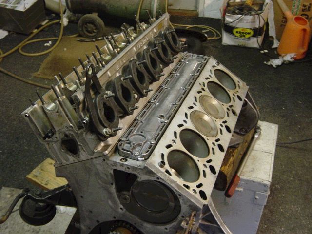
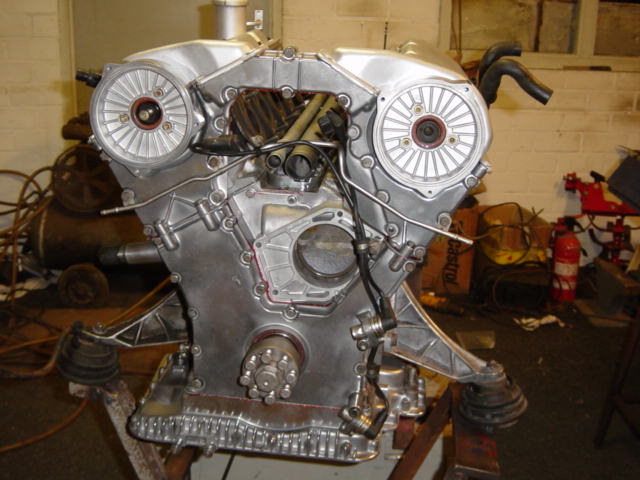
This is a truly magnificent picture. All timing case covers installed, valve covers installed, nice and shiny alloy:
Upper oil pan installed and crankshaft hub installed, notice the crankshaft sensors:
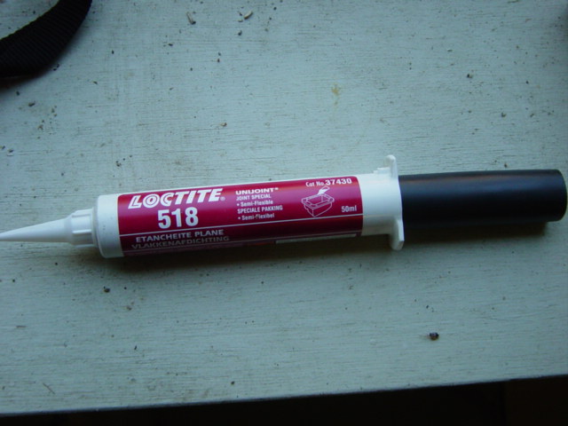
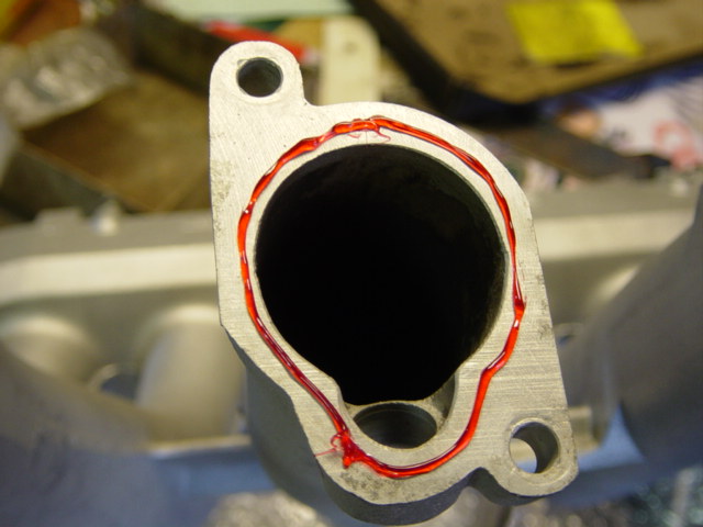
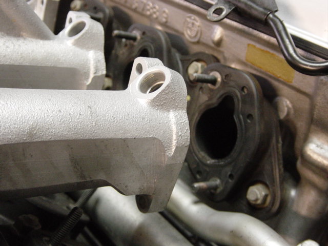
Remember Cor used the old intake gaskets? He did used some sealant between the gaskets and intake manifolds (and used some on new gaskets):
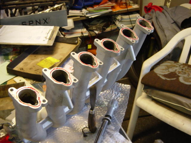
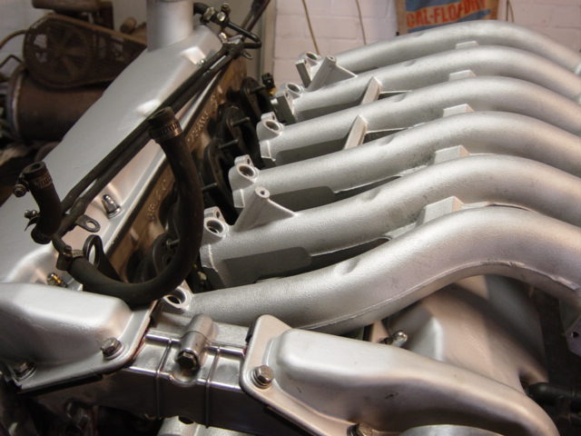
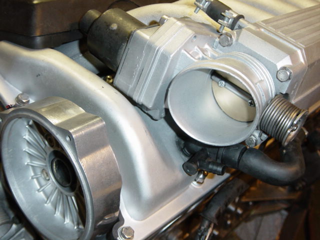
Installing the manifolds, looks like a piece of art eh?
Installing the throttle bodies:
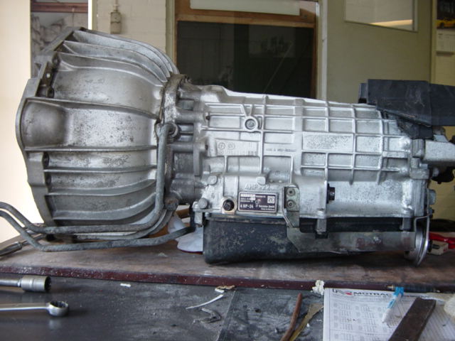
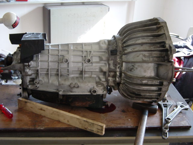
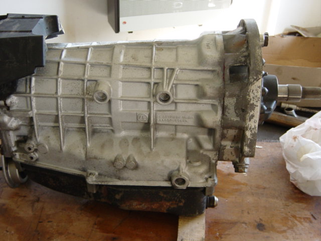
Cor decided also to clean the transmission, replacing the filter and seals:
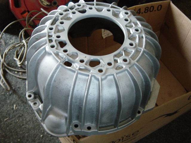
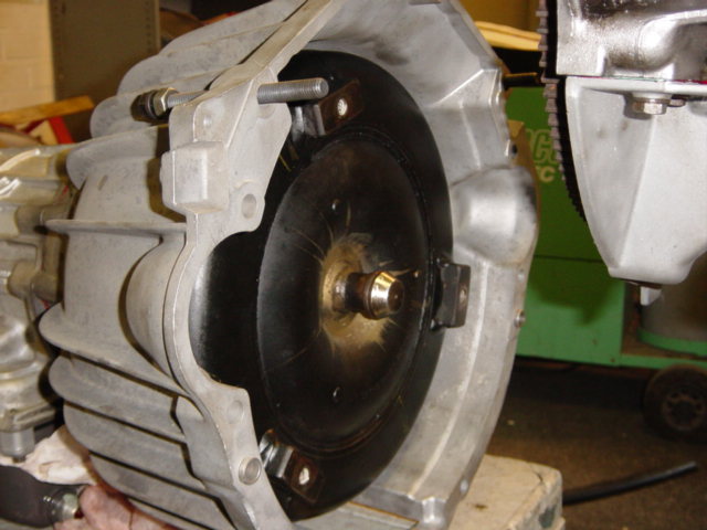
Removal of the bell housing:
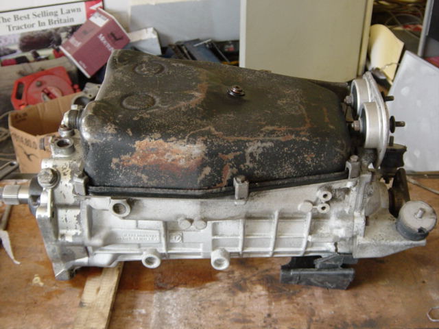
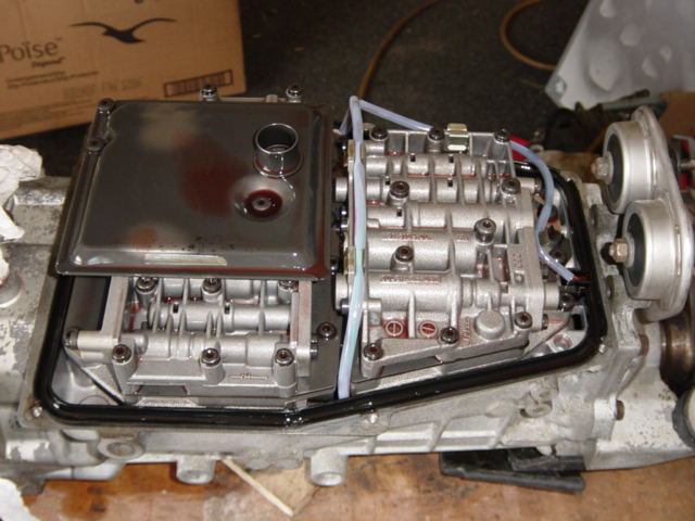
Replacing the filter:
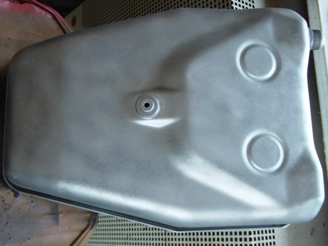
Bead blasting and finishing the oil pan:
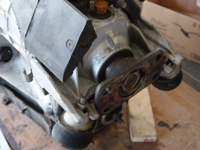
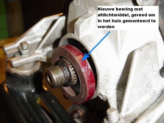
Replacing the front seal:
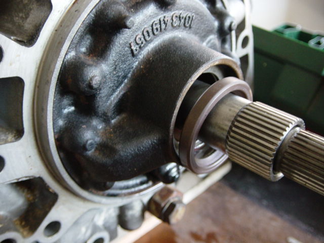
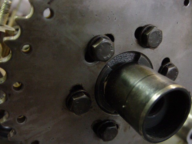
Rear flange:
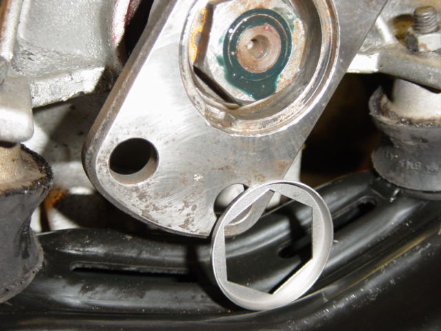
Prying out the locking plate:

After removal of the bolt, the flange slides off:
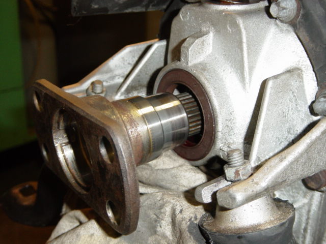
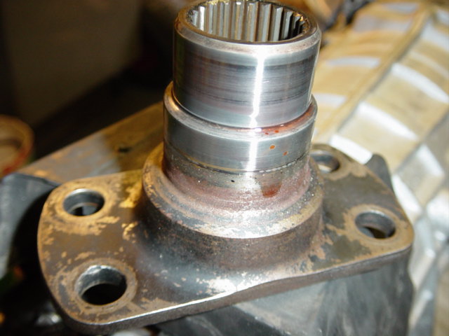
Inspection of the surface:
Installing the new seal, with some sealant between the seal and the housing:
New locking plate:

And one completed transmission, ready to bolt to the engine:
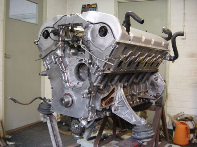
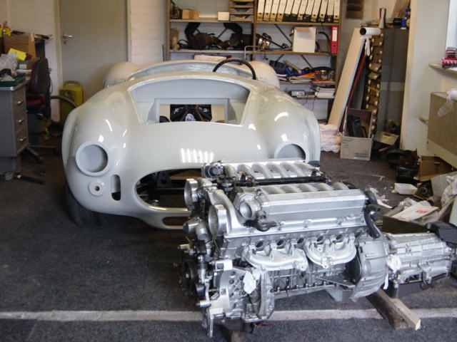
The completed engine, ready to bolt into the cobra:
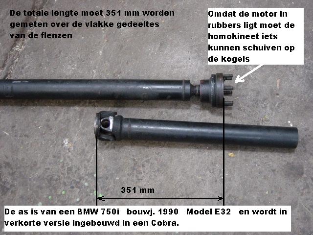
The drive shaft is shortened to fit into the cobra. Total length must be 351mm. The diff of the 750 is reused:
And the marriage:
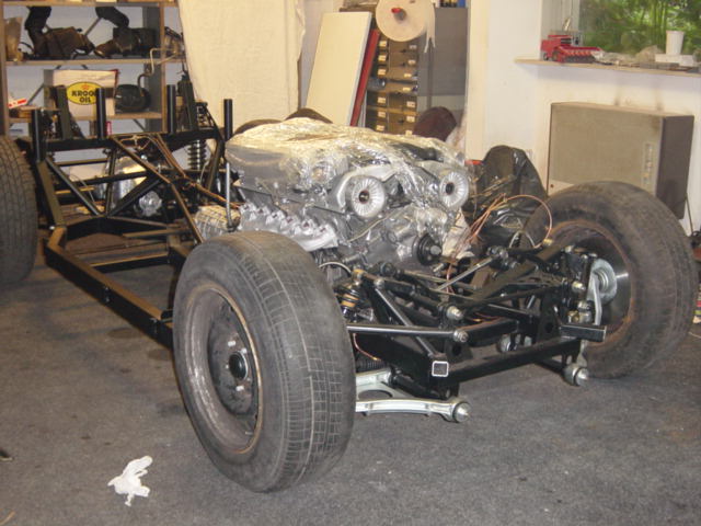
Cor about bolting the BMW V12 into the Cobra:
“The v12 hardly fits under the hood. The v12 is high, very high. Much higher as the plain American 90 degree V8.
I figured I would have lots of space underneath the hood, but that was a mistake. The engine is located behind the front axle.
The radiator of the 750 was way to large and didn’t fit so I had to remove parts of the chassis of the cobra and welded parts of the 750 for the mounting points in place.
There is now actually 10cm clearance between bottom of rad and road. And just 5mm between top of rad and the hood. Still the hood can’t close fully, with a minor change it should close.
This is just one example of the problems I ran into. To fit the rear diff, I had to cut the chassis and re-enforce it again. The drive axle’s also don’t fit without major modifications.
It’s gonna be a hell of a job and I try to solve all the problems one by one. And yes, I have patience and time.”
Cor, again thank you very much for the explanation and photo’s. Keep up the good work and keep us posted.