
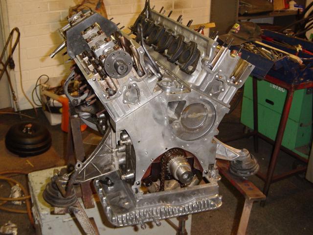
After disassembling all parts and cleaning and spraying them, the hard part of reassembling the engine comes.
New gaskets and seals where
purchased from the BMW dealer:
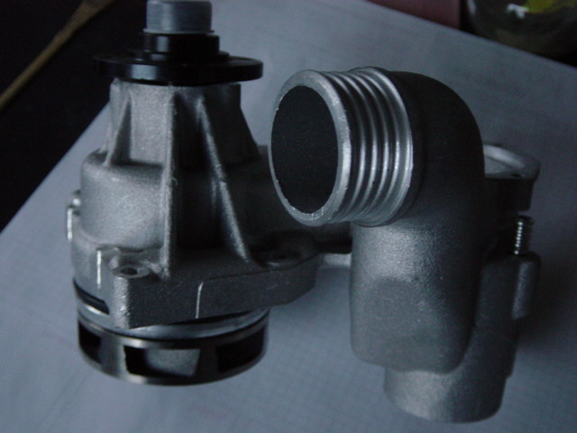
Because the old water pump had
some play, a new pump was ordered:
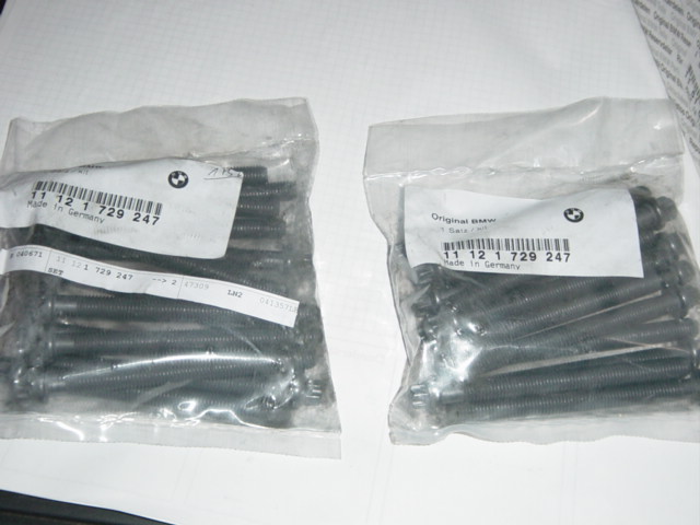
And of course, new sets of head
bolts:
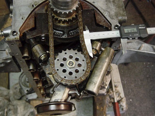
At first Cor decided to
reinstall the oil pump. The chain of the oil pump must be
adjusted, so at first he measured the slack:
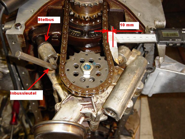
The actual chain slack must be
10mm +/- 2mm and can be adjusted by turning a hex bolt. Cor about
this: 'this
is an interesting design':
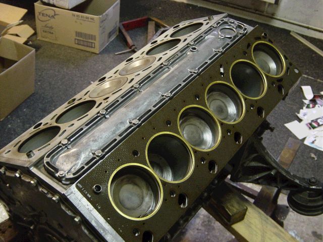
Reassembly begins. The large
coolant cover at the back of the engine already installed, so as
the cover of the central coolant channel. First head gastket in
place. Pay attention to the coolant channels in the head gasket:
the cylinder at the front (rightmost) has larger coolant channel
holes as the cilinders next to it. Probably because this cylinder
is the last cylinder the receiving the coolant, which is pumped
from back to front, so it gets now a higher flow of coolant.
Another detail of this fine piece of machinery:
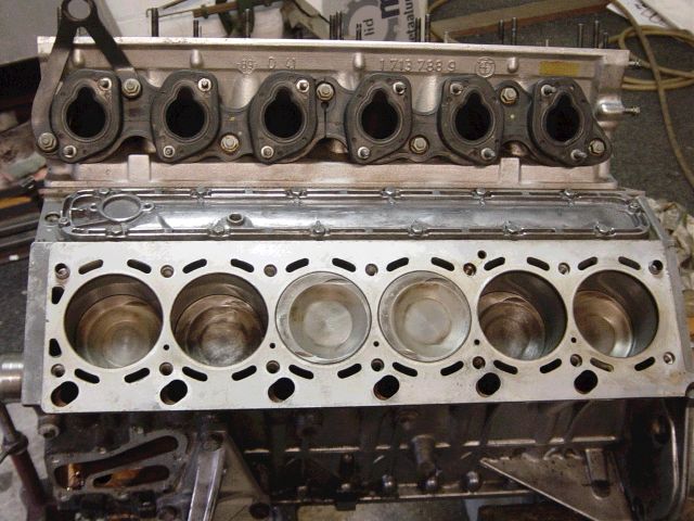
First cylinderhead in place. The
intake gaskets where reused (more on that later):
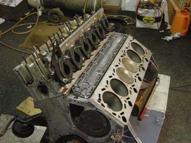
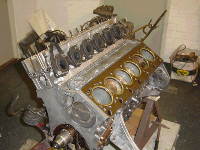
Second head gasket in place:
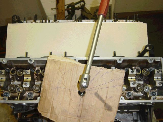
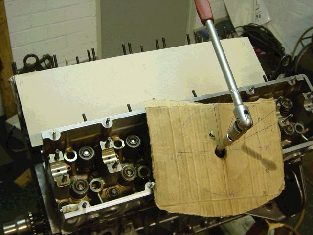
The tightening of the head bolts
goes in 3 stages, where the last 2 stages are app. turning the
head bolts +60 degrees. You need some kind of pointer for this,
but Core made his own home made pointer:
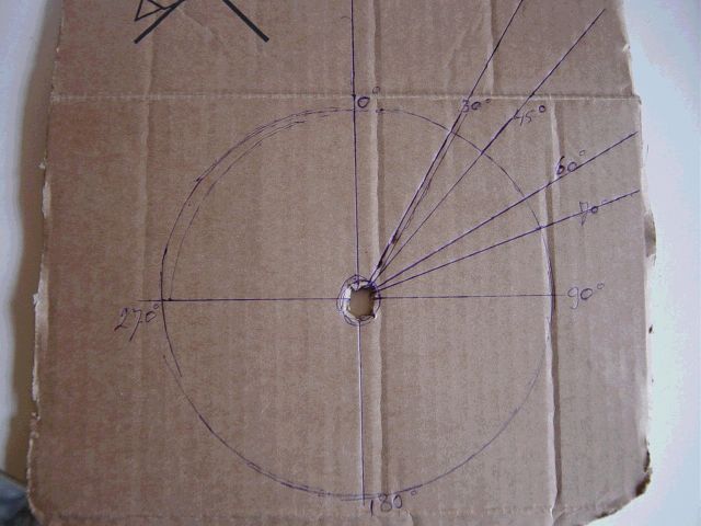
Which worked quite well:
The cardboard at the back used
Cor to make notes so he could identify which bolts where already
tightened 60 degrees and which not (you just don't want to make a
mistake when using yield-to-torque bolts):
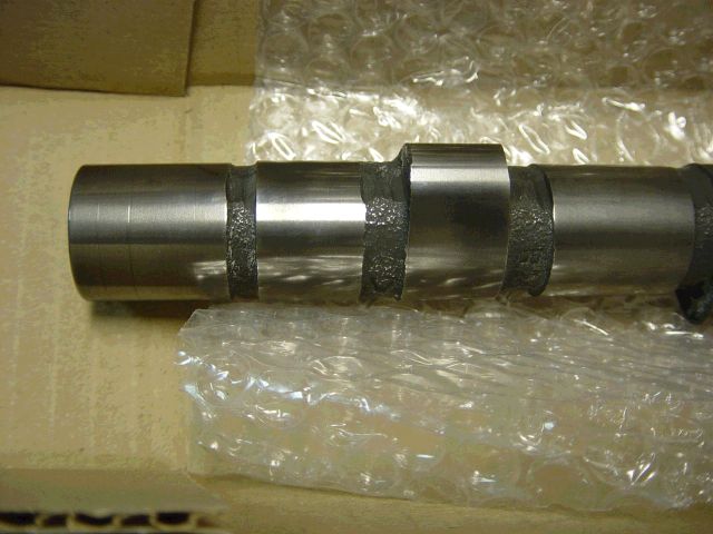
After the head installation,
both cams can be installed. As you may remember from earlier
pictures, both cams where (slighty) worn. New camshaft where just
too expensive so Cor decided to regrind the cams. After
regrinding, the lobes where re-hardened:
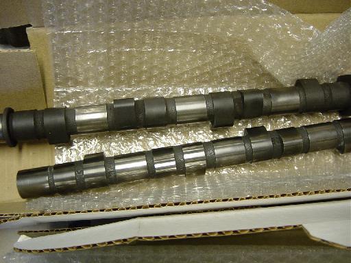
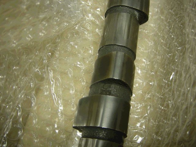
The black 'coating' on the lobes
came from re-hardening the surfaces and was extremely tough to
remove, according to Cor:
In my opinion, regrinding the camshafts is nothing more than removing a slight surface of the camshafts. So its unlike welding the cam lobes, where you build up the lost material (and machine afterwards). I should say this grinding affects the absolute valve lift (the relative valve lift *the distance the valve travels* stays the same because the grinding process is also reducing the diameter of the base circle) because some material is removed from the top of the lobe. Also the rocker position is slightly changed and hydraulic lifter corrects the different height to the cam, but according to Cor this difference is at a minimum.
My knowledge about rebuilding
cams is not extremely good, so maybe a visitor from this site
could elaborate more about this procedure.
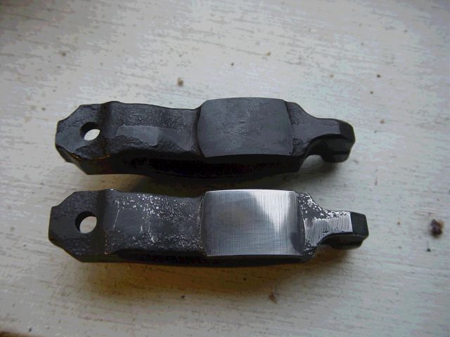
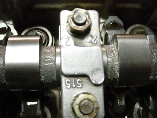
Also the rockers where replaced
by new ones. That is not a bad decision, because the old rockers
where 'worn-in' to the old camshaft surface. The new rockers got
an additional re-harding treatment. Again the black deposits
where very hard to remove:
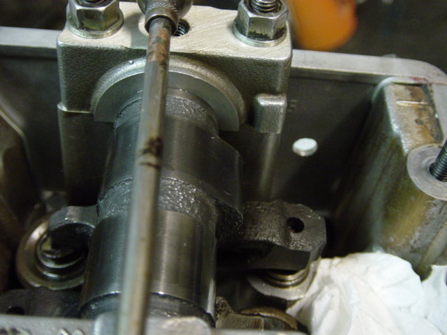
Fitting the cams to the engine.
This is a sensitive job and the bolts must be equally tightened
to prevent damaging the camshaft while tightening it. Cor was
warned for this after the re-hardening process of the camshaft:
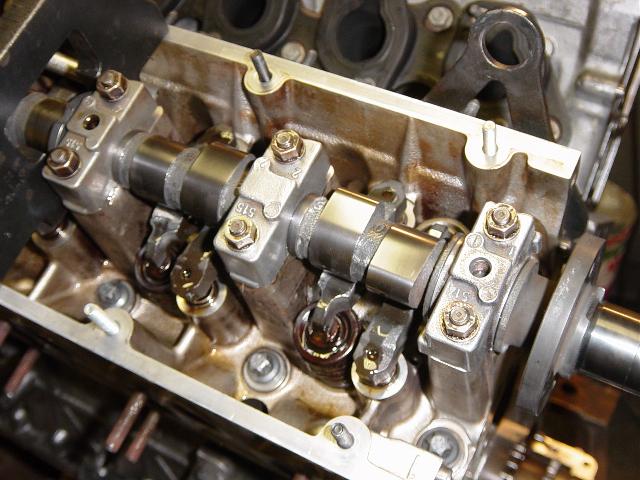
An overview. You'll see the
camshaft locking tool already installed, and the lower oil pan.
This was necessary to put the engine in TDC (locking the flywheel
with a dowel). Cor: 'I didn't know how much clearance there was
between valves and pistons so I wanted to take no risk. I putted
the engine in TDC and installed the camshaft locking tool. After
that, I tightened carefully the camshaft ensuring the valves
(which are depressed while tightening the camshaft) don't hit
some piston.'
After the camshaft installation,
the oil spraying bars could be installed. Ensure the holes are
clean:
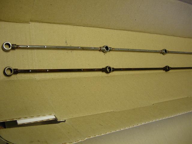
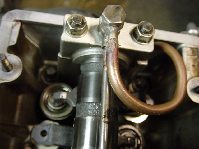
Almost everybody knows about the notorious problem of loose banjo bolts regarding these oil spraying bars. Cor invented a clever system to examine the oil pressure at these bars (which is also the end of the internal oil routing of the engine). He decided to make an extension to the oil bar and attach to the connection a separate oil pressure sender (that is one for each bank) at the back of each cylinder head.
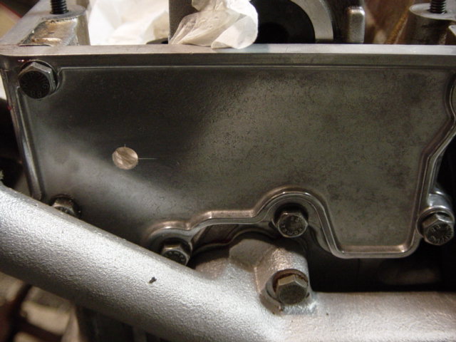
First he ground away the slight
'hump' on the cam bearing cap (picture underneath is without
banjo bolt hole, but you get the point) to get enough clearance
underneath the valve cover:
After grinding the cam bearing
cap, just barely visible at the top of the picture:
Cor bought a larger banjo bolt
and ground the head::
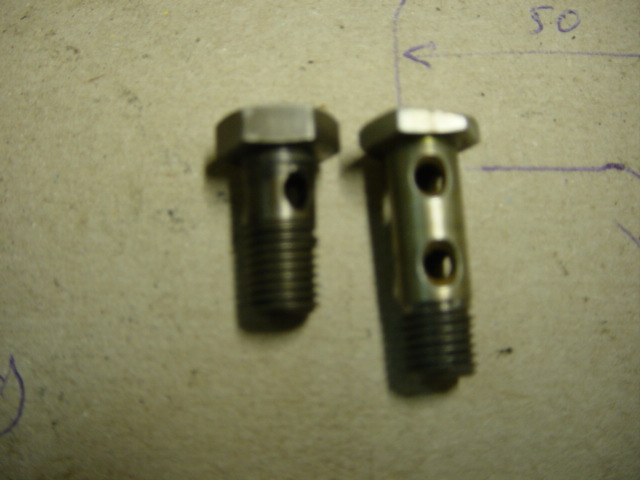
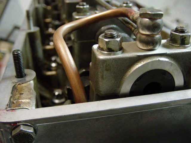
He made a special oil pressure
line with 2 banjo connections:

And drilled a hole in the back
of the cilinder head cover:
And bolted everything together:
If you would like to add any comments, remarks and/or corrections to this procedure, feel free to email Mike Oswald and we'll put it on our site. Share your experiences with us so others may benefit from it.